
Pre-Installation: Box Fill and Circuit Verification
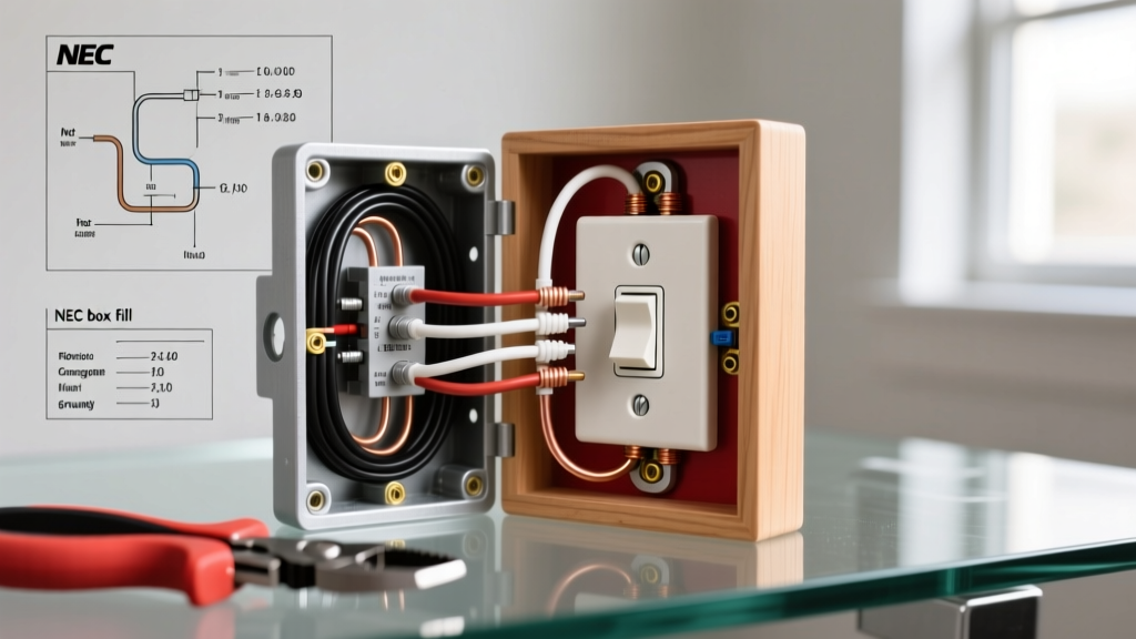
Before you even pick up a wire stripper, a safe and code-compliant installation requires verifying that your existing electrical box can legally accommodate a new device. The National Electrical Code (NEC) Article 314.16 dictates strict "box fill" calculations to prevent overheating and wire damage caused by overcrowding.
To calculate box fill, you must assign a cubic inch value to every item inside the box based on the largest wire gauge present. For 14 AWG wire, the multiplier is 2.0 cubic inches per conductor; for 12 AWG, it is 2.25 cubic inches. You must count each current-carrying conductor (hot and neutral) as one unit. All equipment grounding conductors combined count as a single unit. The receptacle device itself counts as two units based on the largest wire connected to it. Internal cable clamps also count as one unit.
Expert Insight: If you are adding a new outlet to an existing junction box that already houses three 12/2 NM cables and a duplex receptacle, your total box fill is 15.75 cubic inches. If your plastic nail-on box is stamped "18 CU IN," you are legally compliant. If it is a standard 12 CU IN box, you must upgrade to a deeper "old work" box, such as the Carlon B618R-UPC (18 cubic inches), before proceeding.
NEC Code Compliance: GFCI, AFCI, and Tamper Resistance
When you install new electrical outlet hardware in a modern home, standard duplex receptacles are rarely sufficient on their own. The National Fire Protection Association (NFPA) mandates specific protection layers depending on the room's environment and the circuit's purpose.
Ground Fault Circuit Interrupter (GFCI) protection is designed to prevent lethal electric shocks by detecting micro-amp imbalances between the hot and neutral conductors. According to the Consumer Product Safety Commission (CPSC), GFCIs have prevented thousands of electrocutions since their introduction. Arc Fault Circuit Interrupter (AFCI) protection, on the other hand, detects dangerous electrical arcs that cause structural fires, typically originating from damaged cords or loose terminations.
| Location / Circuit Type | GFCI Required (NEC 210.8) | AFCI Required (NEC 210.12) | Tamper-Resistant (TR) |
|---|---|---|---|
| Kitchens (Countertop) | Yes | No (Typically) | Yes |
| Bathrooms | Yes | No | Yes |
| Bedrooms & Living Rooms | No | Yes | Yes |
| Garages & Outdoors | Yes | No | Yes |
| Laundry Areas | Yes | Yes | Yes |
Step-by-Step Installation Protocol
Proper technique separates a safe, lifelong installation from a hidden fire hazard. Follow this exact sequence to ensure mechanical and electrical integrity.
Step 1: De-energize and Verify
Never rely solely on the breaker panel labels. Shut off the circuit breaker and verify the absence of voltage using a non-contact voltage tester, followed by a definitive test with a digital multimeter or solenoid tester like the Fluke T6-1000. Test from hot-to-neutral, hot-to-ground, and neutral-to-ground to ensure no back-fed voltage or bootleg grounds exist on the circuit.
Step 2: Conductor Preparation and Pigtailing
Strip the outer NM-B sheathing so that at least 1/4 inch of sheath extends into the box. Use a precision stripper like the Klein Tools 11054E to remove exactly 3/4 inch of insulation from the 12 AWG or 14 AWG solid copper conductors.
While modern receptacles feature back-wire clamps, the gold standard for reliability is side-wiring with pigtails. If multiple cables enter the box, never use the receptacle itself to daisy-chain the ground wires. NEC 250.148 requires that the grounding continuity remain independent of the device. Use a green wire nut or a Wago 221-413 lever connector to pigtail the bare copper grounds, leaving a single 6-inch tail to terminate on the receptacle's green grounding screw.
Step 3: Termination and Torque Specifications
Since the 2017 NEC update, Article 110.14(D) requires that terminations be tightened to the manufacturer's specified torque using a calibrated tool. Most DIYers simply tighten screws "until they stop," which leads to over-torquing (stripping threads or snapping the screw) or under-torquing (causing thermal expansion loosening and subsequent arc faults).
- Standard 15A Receptacles (e.g., Leviton 5262-W): Typically require 14 in-lbs of torque.
- Spec-Grade 20A Receptacles (e.g., Leviton 8300-W): Typically require 14 to 16 in-lbs of torque.
Use an insulated torque screwdriver, such as the CDI 401SM or the Klein Tools 69000, set precisely to the manufacturer's specification printed on the back of the yoke.
Receptacle Grades: Choosing the Right Hardware
Not all outlets are built equally. Selecting the correct grade ensures longevity and safety, particularly in high-draw areas like kitchens and workshops.
- Residential Grade (e.g., Leviton 5262-W, ~$1.50): Features standard brass contacts and a basic thermoplastic face. Suitable for low-draw areas like bedrooms and living rooms where plugs are rarely removed.
- Spec/Commercial Grade (e.g., Leviton 8300-W, ~$4.50): Engineered with thicker steel yokes, larger brass contact wipers, and high-impact nylon faces. The internal contacts grip plug blades significantly tighter, reducing resistance and heat buildup. Highly recommended for kitchens, garages, and home offices.
- Hospital Grade (e.g., Leviton 5362-IG, ~$12.00): Identified by a green dot on the face. Features an independent, isolated ground path and the tightest blade retention. Generally overkill for residential use unless specifically required for sensitive medical or audio-visual equipment.
Common Failure Modes and Edge Cases
Even experienced DIYers fall victim to specific edge cases that compromise safety. Be vigilant against the following failure modes:
The "Backstab" Push-In Connection
Older or ultra-cheap receptacles feature push-in holes on the back that rely on a small spring-metal wedge to hold 14 AWG wire. These connections are notorious for loosening over time due to thermal cycling, leading to high-resistance faults and melted plastic. Always use the side-binding screw terminals or the screw-clamp back-wiring plates found on commercial-grade devices. Never use push-in backstabs.
Multi-Wire Branch Circuits (MWBC)
If you open a box and find two hot wires (one black, one red) sharing a single neutral white wire, you are dealing with an MWBC. These circuits utilize two 120V legs that are 180 degrees out of phase, allowing the neutral to carry only the unbalanced load. If you install a new outlet and break the neutral tab on the wrong side, or if the two breakers are not tied together with a handle tie (NEC 210.4), you risk overloading the shared neutral wire, which can melt inside the walls without tripping a breaker. Always verify breaker handle ties on MWBCs before working on the receptacles.
Reversed Polarity and Bootleg Grounds
When upgrading older homes, you may encounter two-prong ungrounded outlets. It is a severe code violation and a lethal hazard to install a 3-prong receptacle and use a jumper wire from the neutral screw to the ground screw to "fake" a ground. This is known as a bootleg ground. If the neutral wire ever disconnects upstream, the metal chassis of any plugged-in appliance will become energized at 120V. If no equipment ground exists, you must either run a new ground wire back to the panel, or install a GFCI receptacle and label it "No Equipment Ground" as permitted by NEC 406.4(D)(2).