
Why Install a Switch and Outlet Combo Device?
In modern residential electrical work, space and functionality are paramount. Upgrading a standard single-pole switch to a combination switch and outlet device—such as the highly rated Leviton 5241 15-Amp Duplex Receptacle and Single Pole Switch (retailing around $9.50 to $12.00 in 2026)—is one of the most practical upgrades you can make. This is especially useful in older homes where a bathroom vanity, hallway, or workshop wall has a light switch but lacks a convenient receptacle for a hairdryer, soldering iron, or vacuum.
However, replacing a simple switch with a combo device introduces new circuit requirements. You are no longer just breaking a hot wire; you are managing constant power, switched power, and neutral returns in a single gang box. Understanding the correct wiring diagram for light switch and outlet configurations is critical to prevent short circuits, tripped breakers, and severe fire hazards.
Anatomy of a Combo Device: Terminals and Fins
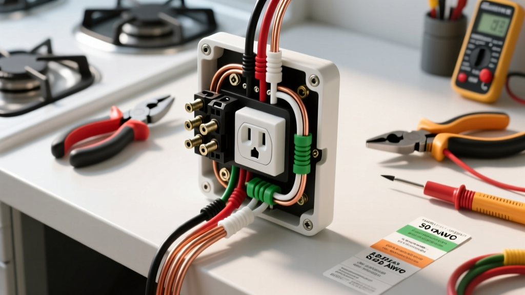
Before touching a wire, you must understand the physical layout of a standard combo device like the Leviton 5241 or the Eaton 470W. Unlike standard receptacles, combo devices feature an asymmetrical terminal layout:
- Brass Terminal (Hot/Line): Receives the continuous 120V incoming power.
- Black Terminal (Switch Leg/Load): Sends switched power to the light fixture.
- Silver Termals (Neutral): Completes the circuit for the outlet receptacle.
- Green Terminal (Ground): Safety earth ground.
- The Brass Fin (Break-off Tab): Located between the hot brass terminal and the black switch terminal. Leave this intact if the outlet needs constant power and the switch controls a separate light. Break it off only if you want the switch to control the outlet itself.
Pre-Installation Checklist and Tool Requirements
Professional electricians do not rely on guesswork. Ensure you have the following specific tools on hand before opening the junction box:
- Non-Contact Voltage Tester: Milwaukee 2201-20 or Klein Tools NCVT-2 (Dual-range for 12-1000V AC).
- Wire Strippers: Klein Tools 11055 (for 14-10 AWG solid/stranded wire).
- Torque Screwdriver: CDI 401SM (set to 14 in-lbs, per UL standard terminal torque specifications for 15A devices).
- Pigtail Wires: 12 or 14 AWG THHN copper, matching your circuit gauge.
Decoding the Wiring Diagram for Light Switch and Outlet
There are two primary scenarios when installing these devices. The most common—and the one we will detail step-by-step—is Scenario A, where the switch controls a separate overhead light, and the outlet remains constantly hot.
Scenario A: Switch Controls Light, Outlet is Always Hot
Requirement: The wall box MUST contain a constant hot, a neutral, a ground, and a switch leg (the wire running up to the light).
| Device Terminal | Wire Color (Standard) | Function |
|---|---|---|
| Brass Screw (HOT) | Black (or Red) | Continuous 120V incoming line power |
| Black Screw (LOAD) | Black (with tape) or Red | Switched leg traveling to the light fixture |
| Silver Screws (NEUTRAL) | White | Neutral return path for the receptacle |
| Green Screw (GROUND) | Bare Copper or Green | Equipment grounding conductor |
Scenario B: Switch Controls the Outlet (Half-Switched)
If you want the switch to turn the bottom receptacle on and off (common for floor lamps), you only need a constant hot, neutral, and ground. You will snap off the brass fin connecting the hot terminals, wire the constant hot to the brass screw, and run a pigtail from the hot to the black switch screw. No separate light fixture wire is needed.
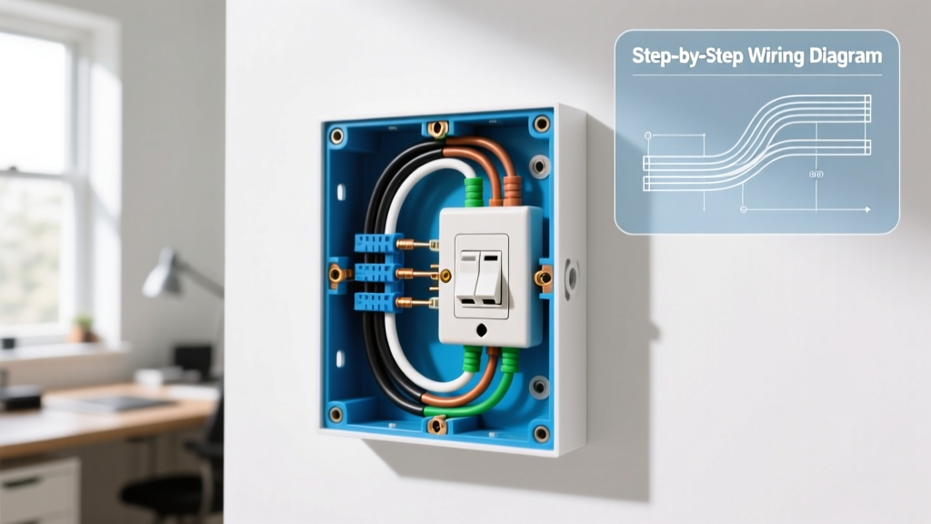
Step-by-Step Installation Guide (Scenario A)
Step 1: Kill Power and Verify
Turn off the circuit breaker at the main panel. Use your Milwaukee or Klein non-contact voltage tester on the existing switch screws. Test a known live circuit first to verify the tester's battery is functioning, then test the target switch. Never skip this step.
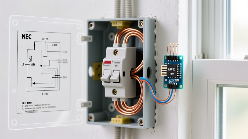
Step 2: Assess Box Fill Capacity (NEC 314.16)
Adding an outlet to a switch box increases the 'box fill' calculation. According to the National Electrical Code (NEC), a combo device counts as two current-carrying conductors. If your box is wired with 14 AWG wire, each conductor counts as 2.0 cubic inches. If the total cubic inch requirement exceeds your physical box volume (usually stamped on the back of plastic boxes, e.g., 18 cu in), you must upgrade to a deeper 'old work' box before proceeding.
Step 3: Prepare and Pigtail the Neutral
Most standard switch boxes do not have the neutral wires connected to the switch; they are simply bundled together in the back of the box with a wire nut.
- Remove the wire nut from the bundled white neutral wires.
- Strip 3/4 inch of insulation from a 14 AWG (or 12 AWG) white pigtail wire using your Klein 11055 strippers.
- Twist the pigtail together with the existing neutral bundle and secure with a purple or yellow Wing-Nut connector.
- Connect the other end of the white pigtail to one of the Silver terminals on the combo device.
Step 4: Wire the Hot and Switch Leg
- Identify the constant hot wire (the one that was live before you turned off the breaker) and the switch leg (the wire going to the light). If unsure, you must temporarily restore power and test with a multimeter, then kill power again.
- Form a 'J-hook' at the end of the constant hot black wire. Loop it clockwise around the Brass terminal screw. This ensures the screw pulls the wire tighter as you tighten it.
- Connect the switch leg wire to the Black terminal screw.
- Ensure the brass break-off fin between the brass and black terminals is INTACT.
Step 5: Ground and Mount
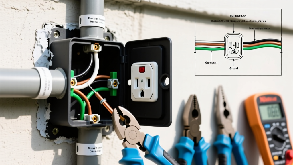
Connect the bare copper ground wire to the Green terminal. If the box is metal, you must also run a grounding pigtail to the metal box's grounding clip. Carefully fold the wires in a 'Z' pattern (grounds first, then neutrals, then hots) to avoid pinching insulation. Drive the mounting screws and torque them evenly. Restore power and test both the receptacle (with a 3-prong tester) and the light switch.
Troubleshooting Edge Cases and Failure Modes
Expert Warning: The 'Switch Loop' Trap
In homes built before the 2011 NEC update, electricians often used a 'switch loop' where the white wire was re-identified as a hot wire traveling up to the light, and the black wire returned as the switched hot. In this scenario, there is no neutral wire in the switch box. You cannot install an always-hot outlet combo device in a switch loop box without pulling a new neutral wire from the light fixture or another circuit. Attempting to use the ground wire as a neutral is a severe code violation and a lethal shock hazard.
Failure Mode 1: GFCI Tripping on Shared Neutrals
If the circuit you are tapping into is a Multi-Wire Branch Circuit (MWBC) sharing a neutral with another hot leg, plugging a high-draw appliance into your new outlet may cause the upstream GFCI or AFCI breaker to trip. The Consumer Product Safety Commission (CPSC) strongly advises verifying that the neutral you are pigtailing is dedicated solely to the 120V leg feeding your combo device.
Failure Mode 2: Backstabbing vs. Screw Terminals
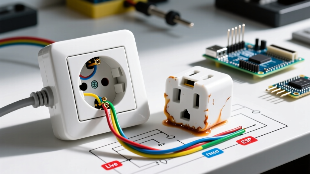
Never use the push-in 'backstab' holes on the back of a combo device. The internal spring-loaded grips degrade over time, especially under the thermal expansion cycles caused by high-draw appliances like space heaters or hair dryers. Always use the side screw terminals, torqued to the manufacturer's specification (typically 14 in-lbs for 15A devices).
2026 NEC Code Compliance and Safety Standards
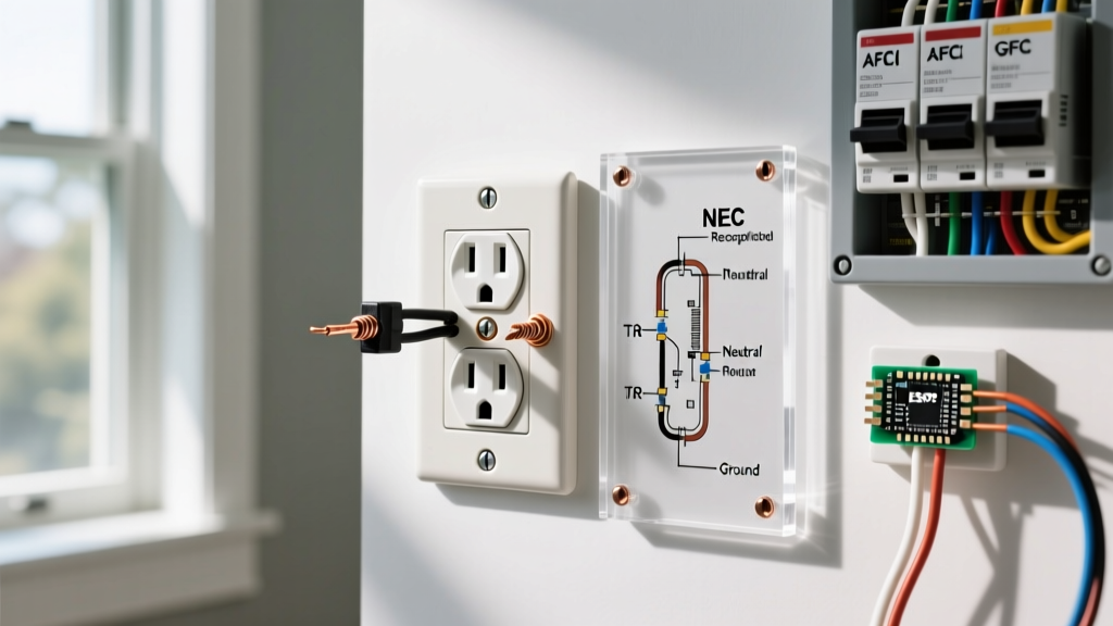
When performing this upgrade in 2026, you must adhere to the latest localized adoptions of the NEC. If you are installing this combo device in a bathroom, kitchen, garage, or unfinished basement, the receptacle portion must be GFCI protected. Standard combo devices (like the Leviton 5241) do not have built-in GFCI protection. Therefore, you must either ensure the circuit is protected by a GFCI breaker in the main panel, use an upstream GFCI receptacle, or purchase a specialized (and significantly more expensive) GFCI combo device, such as the Leviton GFSW1-W.
Furthermore, if the installation is in a bedroom or living area, AFCI (Arc-Fault Circuit Interrupter) protection is mandatory. Always pull local permits for electrical modifications, as adding a receptacle changes the load profile and intended use of the junction box, which requires inspection to ensure compliance with modern fire safety standards.