
The Dual Meaning of 'Screwing In' an Outlet
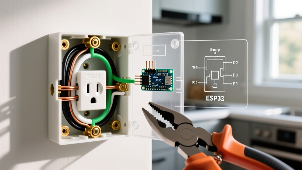
When DIYers and junior electricians search for how to properly screw in electrical outlet components, they are often conflating two entirely distinct, code-governed processes. The first is electrical termination: securing the current-carrying and grounding conductors to the device's terminal screws. The second is mechanical mounting: physically screwing the receptacle yoke into the junction box. Both phases are strictly regulated by the National Electrical Code (NEC) and the National Fire Protection Association (NFPA), and failure in either can lead to arcing, thermal runaway, or catastrophic fire.
This guide breaks down the exact NEC mandates, torque specifications, and mechanical clearances required to terminate and mount a standard 15A or 20A duplex receptacle in 2026.
Phase 1: Terminal Screw Wire Termination (NEC 110.3 & 110.14)
The terminal screws on a standard receptacle (such as the Leviton T5262 or Eaton 5266) are engineered to specific metallurgical tolerances. How you wrap, strip, and tighten the wire around these screws is not a matter of preference; it is a matter of code compliance.
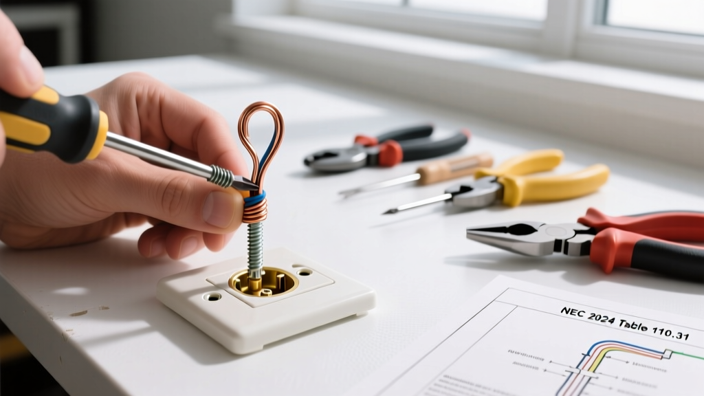
The Clockwise Loop Mandate
NEC 110.3(B) requires all equipment to be installed in accordance with the manufacturer's instructions. Every major UL-listed receptacle manufacturer specifies that when side-wiring (looping the wire around the terminal screw), the loop must be formed in a clockwise direction.
Expert Insight: When you tighten a right-handed (clockwise-threaded) screw over a clockwise wire loop, the friction pulls the wire tighter around the screw shaft. If you loop it counter-clockwise, the tightening action pushes the wire outward, potentially slipping it past the screw head and creating a high-resistance, fire-hazard connection.
Precision Wire Stripping
Do not guess your strip length. On the back of every UL-listed receptacle, there is a molded 'strip gauge'. For 14 AWG and 12 AWG solid copper wire, this gauge typically dictates a strip length of exactly 5/8" to 3/4". Exposing too much bare copper creates a shock hazard and violates NEC 110.12 (Mechanical Execution of Work). Leaving too much insulation prevents the wire from seating fully under the screw head, leading to 'cold flow' loosening over time. Use a precision tool like the Klein Tools 11055 to score and strip the insulation cleanly without nicking the copper conductor.
Phase 2: The Torque Requirement (NEC 110.14(D))
Historically, electricians were taught to tighten terminal screws until they were 'snug.' The modern NEC has eliminated this ambiguity. Under NEC 110.14(D), connections must be tightened to the manufacturer's specified torque using a calibrated torque tool.
As circuits undergo thermal cycling (heating under load, cooling when idle), under-torqued screws loosen, increasing resistance and generating lethal heat. Over-torqued screws can strip the brass threads or crush softer aluminum conductors.
Standard Torque Specifications
- 15A/20A Standard Receptacles (Side-Wire): Typically 12 to 14 inch-pounds (in-lbs).
- 15A/20A Receptacles (Back-Wire Clamp): Typically 14 to 16 in-lbs.
- Ground Terminal Screw: Typically 12 in-lbs.
Note: Always verify the exact torque value printed on the device packaging or manufacturer spec sheet. To achieve this, professionals use inch-pound torque screwdrivers, such as the CDI Torques 1002MFRMH or Wiha 645P10, rather than standard hand screwdrivers.
Connection Methods: Code Compliance & Pull-Out Force
Not all 'screw in electrical outlet' wiring methods are created equal. The table below compares the three primary termination methods found on modern receptacles.
| Method | How It Works | NEC / UL Status | Max Pull-Out Force |
|---|---|---|---|
| Side-Wiring (Loop) | Wire is stripped, looped clockwise around the terminal screw, and tightened. | Fully Compliant. The traditional, universally accepted method. | ~60-80 lbs (when torqued properly) |
| Back-Wiring (Screw Clamp) | Wire is inserted straight into a hole; a screw tightens a internal pressure plate onto the wire. | Fully Compliant. Preferred for commercial work and pigtailing multiple wires. | ~120-150 lbs (Superior grip) |
| Push-In (Backstab) | Wire is pushed into a hole where a spring-loaded brass clip bites into the copper. | UL Listed only for 14 AWG solid wire on 15A circuits. Prohibited for 12 AWG and 20A circuits. Highly discouraged by inspectors. | ~20-30 lbs (Prone to thermal failure) |
Phase 3: Physical Mounting Screws (NEC 406.5 & 314.20)
Once the wires are terminated, the device must be physically screwed into the junction box. This is where severe mechanical and electrical hazards often occur due to improper screw selection.
The 'Too-Long Screw' Hazard
Receptacles are mounted to metal or plastic junction boxes using 6-32 UNC machine screws. The screws provided in the receptacle packaging are typically exactly 1 inch long.
Edge Case Failure Mode: If a junction box is buried deep behind drywall, an amateur might swap the 1-inch screw for a 2-inch or 3-inch drywall screw or machine screw to reach the box ears. If the wires inside the metal box are pushed near the mounting holes, the sharp point of the over-long screw can pierce the wire insulation as it is driven into the box. This instantly energizes the metal box, the drywall mud ring, and the receptacle cover plate with 120V, creating an invisible, lethal shock hazard.
Code-Compliant Solutions for Deep Boxes
If the box is recessed more than 1/4 inch (non-combustible surfaces) or 1/8 inch (combustible surfaces) from the wall finish, NEC 406.5 dictates you cannot simply use longer screws. You must use one of the following:
- Box Extenders (NEC 314.20): Slip a plastic or metal box extender ring over the existing box to bring the mounting ears flush with the wall surface.
- Plaster Ears / Device Levelers: Attach extendable plaster ears to the receptacle yoke to bridge the gap to the drywall, allowing the standard 1-inch screws to securely engage the original box ears.
Step-by-Step Code-Compliant Installation Flow
Follow this exact sequence to ensure your installation passes municipal inspection and operates safely for decades.
- Verify Power: Use a non-contact voltage tester (e.g., Fluke 2AC) and a multimeter to confirm the circuit is de-energized.
- Prepare Conductors: Cut wires to leave exactly 6 inches of length extending past the front edge of the junction box. Strip 5/8" of insulation using the device's built-in gauge.
- Form & Terminate: Form a clockwise loop using needle-nose pliers. Seat the loop under the side terminal screw. (Alternatively, use the back-wire clamp holes for straight insertion).
- Apply Torque: Use an inch-pound torque screwdriver set to the manufacturer's spec (usually 14 in-lbs) to secure the terminal and ground screws.
- Fold & Mount: Neatly fold the wires in a zig-zag pattern into the back of the box. Align the yoke with the box ears.
- Secure Device: Drive the provided 1-inch 6-32 machine screws into the mounting ears. If the device sits deeper than 1/4" behind drywall, install a box extender first.
Frequently Asked Questions
Can I use drywall screws to mount an outlet to a wooden stud?
No. Drywall screws are brittle, lack the shear strength required for structural mounting, and are not approved for securing electrical boxes or devices. Furthermore, if attaching a metal box or device yoke, drywall screws do not provide the reliable grounding path required by code. Always use the provided 6-32 machine screws for device-to-box mounting.
Is it code-compliant to put two wires under one side terminal screw?
Generally, no. Unless the terminal screw and pressure plate are explicitly UL-listed and marked for two conductors, you must use a pigtail. Connect the two circuit wires and a short pigtail wire together using a wire nut or WAGO connector, then land the single pigtail under the receptacle's terminal screw. OSHA and NEC guidelines (OSHA Electrical Safety Standards) strictly enforce single-conductor terminations unless the hardware is specifically rated otherwise.
Why does my outlet feel warm to the touch?
A warm outlet faceplate indicates a high-resistance connection. This is almost always caused by a loose terminal screw (under-torqued), a counter-clockwise loop that has slipped, or the use of push-in 'backstab' connections that have lost their spring tension over years of thermal cycling. Immediately shut off the breaker, remove the device, and re-terminate the wires using the side-screw or back-wire clamp method with a calibrated torque screwdriver.