
The Critical Code Context: Why the 3-Prong Dryer Outlet is Legacy
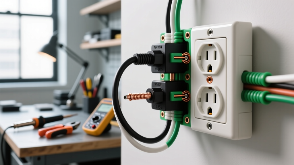
If you are searching for a wiring diagram for dryer outlet 3 prong configurations, you are likely dealing with an older home's laundry room or replacing a damaged legacy receptacle. The 3-prong dryer outlet, technically known as a NEMA 10-30R, was the standard for electric clothes dryers for decades. However, from a modern electrical safety and code compliance perspective, this configuration is considered obsolete and inherently hazardous for new installations.
The fundamental safety flaw in a 3-prong setup is the absence of a dedicated equipment grounding conductor. In a NEMA 10-30 circuit, the neutral wire (the center prong) is forced to do double duty: it carries the unbalanced return current from the dryer's 120V components (like the timer and drum motor) while simultaneously serving as the safety ground for the dryer's metal chassis. If that neutral wire breaks, loosens, or develops high resistance, the metal exterior of your dryer can become energized at 120V or 240V, creating a lethal shock hazard.
Recognizing this danger, the National Fire Protection Association (NFPA) updated the National Electrical Code (NEC) in 1996 to mandate 4-prong outlets (NEMA 14-30) with a dedicated ground wire for all new dryer installations. According to the Electrical Safety Foundation International (ESFI), proper grounding and bonding are critical to preventing electrical fires and electrocution in high-draw appliance circuits.
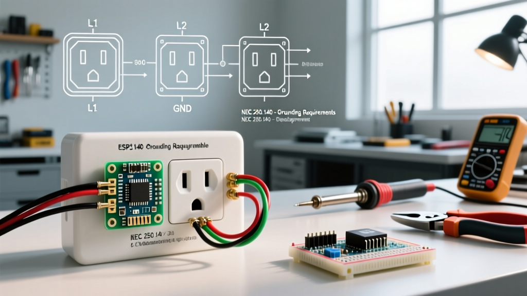
NEC Article 250.140 Exception 1: For existing branch-circuit installations only, where an equipment grounding conductor is not present, the frame of an electric clothes dryer shall be permitted to be connected to the grounded circuit conductor if the circuit originates at the service equipment and the grounded conductor is not smaller than 10 AWG copper or 8 AWG aluminum.
Anatomy of a Wiring Diagram for Dryer Outlet 3 Prong (NEMA 10-30R)
When wiring or replacing an existing 3-prong receptacle (such as the Leviton 278-S00 or Hubbell HBL278), you are working with a 240V/120V split-phase circuit protected by a 30-amp double-pole breaker. The wiring diagram consists of three active terminals:
- Terminal X (Left Hot): Connects to the Black wire. This provides 120V relative to the neutral and 240V relative to Terminal Y.
- Terminal Y (Right Hot): Connects to the Red wire. This provides the second phase of the 240V circuit, powering the main heating element.
- Terminal W (Center Neutral): Connects to the White wire. This is the grounded conductor. It completes the 120V circuit for the dryer's electronics and, via a bonding strap inside the dryer, acts as the chassis ground.
Note: In very old legacy installations using 10/2 SE (Service Entrance) cable, the bare wire was used as the neutral. In later installations using 10/3 NM-B (Romex), the white wire is the neutral, and the bare ground wire is either capped off or illegally bonded to the neutral terminal. Never bond the bare ground to the neutral terminal on the receptacle itself; the bonding must only occur at the main service panel or inside the dryer's terminal block.
Comparison Matrix: 3-Prong (NEMA 10-30) vs. 4-Prong (NEMA 14-30)
| Feature | NEMA 10-30 (3-Prong Legacy) | NEMA 14-30 (4-Prong Modern) |
|---|---|---|
| Prongs / Wires | 3 Prongs / 3 Wires | 4 Prongs / 4 Wires |
| Voltage / Amperage | 125/250V / 30 Amps | 125/250V / 30 Amps |
| Grounding Method | Neutral wire acts as ground (Bonded at dryer) | Dedicated equipment grounding conductor |
| NEC Compliance (New) | Prohibited for new installs since 1996 | Required for all new installations |
| Shock Hazard Risk | High (if neutral fails, chassis becomes live) | Low (dedicated ground protects chassis) |
| Cable Type Required | 10/2 SE or 10/3 NM-B (ground capped) | 10/3 NM-B or 4-wire THHN in conduit |
Step-by-Step: Safely Replacing an Existing 3-Prong Receptacle
If your existing NEMA 10-30R is melted, loose, or damaged, the NEC "grandfather clause" allows you to replace it with a new 3-prong receptacle without forcing a full circuit upgrade. However, you must follow strict safety protocols. As outlined by OSHA wiring design and protection standards, proper termination and lockout procedures are non-negotiable.
- Lockout/Tagout the Circuit: Turn off the 30A double-pole breaker (e.g., Square D HOM230 or Eaton BR230) in your main panel. Apply a physical lockout tag to prevent accidental re-energizing.
- Verify Zero Voltage: Use a CAT III rated multimeter. Test between the two hot slots (should read 0V), and between each hot slot and the neutral slot (should read 0V). Never rely solely on a non-contact voltage tester for 240V circuits.
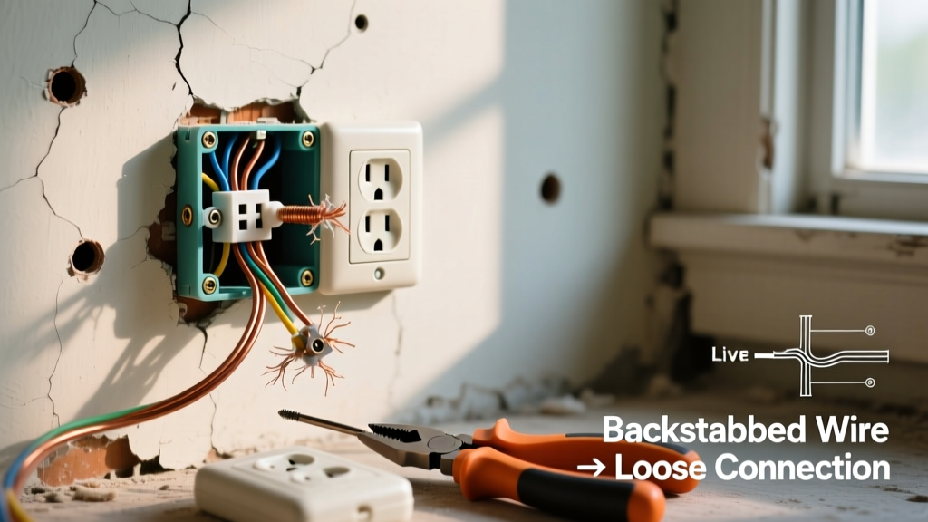
- Inspect the Wiring and Box: Pull the old receptacle out. Look for thermal damage, melted wire insulation, or scorch marks on the drywall. If the wire insulation is brittle or melted, you must cut back the damaged section and splice in new wire using a deep junction box, or replace the entire cable run.
- Prepare the Conductors: Strip exactly 3/4 inch of insulation from the 10 AWG copper wires. Do not nick the copper; a nicked wire creates a hot spot and a future fire hazard under a 30A continuous load.
- Terminate with Precision Torque: Connect Black to X, Red to Y, and White to W. Use a dial torque screwdriver to tighten the terminal screws to the manufacturer's specification—typically 18 in-lbs for 10 AWG wire on standard 30A receptacles. Under-torquing causes arcing; over-torquing strips the threads or crushes the wire strands.
- Secure and Test: Push the wires neatly into the deep junction box, mount the receptacle, and install the cover plate. Restore power and test the outlet with a multimeter to confirm 240V across the hots and 120V from each hot to the neutral.
Known Failure Modes & Lethal Edge Cases
The Broken Neutral Hazard
The most dangerous failure mode in a 3-prong dryer circuit is an open neutral. If the white wire disconnects from the receptacle terminal or breaks inside the dryer's terminal block, the 120V return path is lost. Because the dryer's chassis is bonded to this neutral wire via the bonding strap, the chassis will immediately rise to 120V potential relative to the earth. If a user touches the dryer and a grounded object (like a washing machine or water pipe) simultaneously, they complete the circuit, resulting in severe electrocution.
Aluminum Wire Oxidation and Creep
Many homes built in the 1960s and 1970s used aluminum branch circuit wiring to save costs. Aluminum expands and contracts more than copper under thermal load, leading to "creep" under terminal screws. Furthermore, aluminum oxidizes rapidly when exposed to air, creating a high-resistance layer that generates intense heat. If your 3-prong outlet is fed by aluminum wire, the receptacle must be rated CO/ALR (Copper-Aluminum Revised). You must also apply an antioxidant compound like Noalox to the stripped wire before termination to prevent oxidation and subsequent thermal failure.
The Verdict: Should You Upgrade to a 4-Prong Setup?
While understanding the wiring diagram for a 3-prong dryer outlet is essential for maintaining legacy systems, the ultimate goal for any homeowner should be upgrading to a 4-prong NEMA 14-30 configuration. Upgrading requires pulling a new 10/3 NM-B cable (which includes Black, Red, White, and a Bare Ground) from the panel to the laundry room, installing a new 4-prong receptacle, and swapping the dryer's power cord and internal bonding strap.
This upgrade separates the neutral current from the safety ground, entirely eliminating the open-neutral shock hazard. If you are unsure about your home's wiring, panel capacity, or local code amendments, hire a licensed electrician. Electrical safety is not an area for trial and error; the cost of a professional upgrade is a fraction of the cost of a preventable electrical fire.