
The Anatomy of a 5-Pin Winch Rocker Switch
When wiring an ATV, UTV, or marine winch, understanding the control circuit is critical for reliable operation. A standard winch motor draws anywhere from 150A to over 400A under heavy load. The 5-pin rocker switch (such as the popular Nilight 90014E-B or Bussmann equivalents, typically retailing between $8 and $14 in 2026) does not carry this main motor current. Instead, it acts as a low-amperage trigger, sending a 2A to 5A control signal to the winch solenoid contactor (e.g., Warn 87665, ~$65).
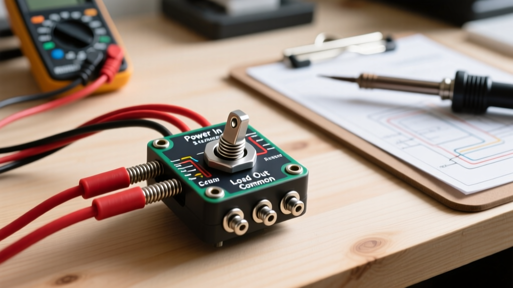
Before testing, you must understand the standard 5-pin layout found on most modern DPDT (Double Pole, Double Throw) center-off winch switches:
- Pin 1 (Top Left): 12V+ Power Input. This receives fused 12V power directly from the battery or an accessory bus.
- Pin 2 (Top Right): Load 1 / Winch IN. This sends the 12V signal to the solenoid terminal responsible for spooling the cable in.
- Pin 3 (Bottom Left): Illumination. Connects to the vehicle's dash dimmer circuit to illuminate the switch border when headlights are on.
- Pin 4 (Bottom Right): LED Ground. Completes the circuit for the rocker's internal indicator LEDs.
- Pin 5 (Center): Load 2 / Winch OUT. Sends the 12V signal to the solenoid terminal for spooling the cable out.
Critical Safety Warning: Never route the main winch motor power through the rocker switch. The switch contacts are rated for a maximum of 20A. Attempting to bypass the solenoid contactor and wire the motor directly to the switch will result in immediate melting, potential fire, and severe injury. Always use 12 AWG wire for the switch control circuit and 2 AWG or 4 AWG wire for the main motor power.
Essential Diagnostic Tools for 2026
Proper inspection requires more than a basic test light. To accurately diagnose voltage drops and internal contact resistance, assemble the following tools:
- True-RMS Digital Multimeter (DMM): A Fluke 117 or Klein Tools MM400 is essential for accurate DC voltage and low-resistance continuity readings.
- Wire Piercing Probes: Allows you to test 12V signals at the solenoid without stripping back insulation, which prevents future corrosion.
- 12V Automotive Test Light: Useful for quick, visual verification of power presence at the solenoid coils.
- Dielectric Grease & Marine Heat Shrink: Required for resealing connections post-inspection.
Step-by-Step Continuity and Voltage Testing
Follow this systematic approach to verify the integrity of your 5 pin rocker switch wiring diagram for winch applications.
Phase 1: Bench Testing the Switch (Continuity)
If the winch is unresponsive, isolate the switch first. Remove the switch from the dash panel and disconnect the wiring harness.
- Set your DMM to the Ohms (Ω) setting, ensuring it is zeroed.
- Place one probe on Pin 1 (Power In) and the other on Pin 2 (Winch IN).
- Press the rocker switch UP. The multimeter should read less than 1.0 ohm. If it reads OL (Open Loop) or fluctuates wildly, the internal copper contacts are pitted or broken.
- Move the second probe to Pin 5 (Winch OUT) and press the switch DOWN. Verify the reading is again under 1.0 ohm.
- Release the switch to the center OFF position. Both circuits should read OL, confirming the switch is properly isolating the solenoid coils when idle.
Phase 2: In-Circuit Voltage Drop Testing
Continuity tests only tell half the story. A switch might pass a continuity test with no load but fail catastrophically under the actual draw of the solenoid coils. According to Fluke's guide on voltage drop, testing under load is the only way to find hidden resistance caused by corrosion or loose crimps.
- Reconnect the switch and ensure the winch solenoid is wired.
- Set your DMM to DC Volts.
- Place the red probe on the battery side of the 20A inline ATC fuse, and the black probe on Pin 2 at the back of the switch.
- Press the switch UP (Winch IN). The solenoid should click, and the DMM should read a voltage drop of less than 0.2V.
- If the voltage drop exceeds 0.5V, you have excessive resistance in the 12 AWG control wire, a corroded fuse holder, or failing internal switch contacts. As noted by AA1Car's automotive electrical diagnostics, even a 1-volt drop in a 12V control circuit can starve a solenoid coil of the amperage needed to fully engage the heavy-duty internal plunger, resulting in a 'clicking but not pulling' symptom.
Inspecting the Winch Relay and Solenoid Pack
If your 5-pin switch tests perfectly, the fault likely lies in the solenoid contactor pack. Winch solenoids are essentially heavy-duty relays. Over time, the internal copper discs arc and pit, leading to high resistance or a 'stuck' closed state.
To test the solenoid coils, disconnect the control wires from the switch (Pins 2 and 5). Set your DMM to Ohms and measure the resistance across the small solenoid terminals. A healthy winch solenoid coil typically reads between 40 and 60 ohms. If you read 0 ohms, the coil has an internal short. If you read OL, the coil wire is severed internally. Furthermore, inspect the main 250A ANL fuse and the 2 AWG battery cables for green copper oxide corrosion, which is notorious in marine and UTV environments.
Common Failure Modes & Troubleshooting Matrix
Use the following matrix to quickly cross-reference your symptoms with verified electrical faults.
| Symptom | Probable Cause | Multimeter Reading | Solution |
|---|---|---|---|
| Winch clicks but drum doesn't turn | Solenoid engaging, but main motor contacts pitted or motor brushes worn. | High voltage drop (>1V) across main solenoid lugs under load. | Rebuild or replace the solenoid contactor pack; inspect motor brushes. |
| Switch gets hot to the touch | Backfeed from a stuck solenoid pulling >20A through the 12 AWG control circuit. | Continuous 12V+ reading on Pin 2 or 5 even when switch is OFF. | Replace the fused control wire, install a new 20A ATC fuse, and replace the solenoid. |
| LEDs illuminate, but winch doesn't move | LED ground (Pin 4) is intact, but Power In (Pin 1) has a broken crimp. | OL on continuity test between Pin 1 and Pin 2/5. | Re-crimp the 12V+ supply wire using an adhesive-lined marine heat shrink connector. |
| Winch spools OUT, but not IN | Internal failure of the 'UP' contact pad inside the rocker switch. | OL between Pin 1 and Pin 2 when pressed UP; <1Ω between Pin 1 and Pin 5 when DOWN. | Replace the 5-pin rocker switch (do not attempt to open and repair internal springs). |
Weatherproofing and Edge Cases in Harsh Environments
For UTVs, snowplows, and marine winches, water ingress is the primary killer of 5-pin rocker switches. While many modern switches boast an IP68 front-panel rating, the rear spade terminals are completely exposed to mud, salt spray, and condensation.
When finalizing your 5 pin rocker switch wiring diagram for winch setups, always apply a generous coat of dielectric grease to the spade terminals before pushing the wiring harness boots into place. For extreme environments, wrap the entire rear terminal block in self-amalgamating silicone tape. This creates a seamless, waterproof barrier that prevents the galvanic corrosion responsible for 80% of premature winch switch failures. Finally, ensure your control circuit ground (Pin 4) is tied to a clean, bare-metal chassis ground or a dedicated marine ground busbar, rather than daisy-chaining it to other high-draw accessories, which can cause LED flickering and erratic solenoid behavior.