
Understanding and Installing Common US Electrical Outlet Types
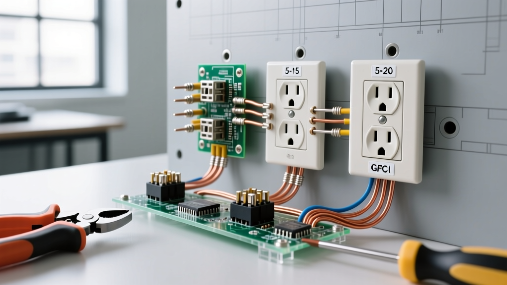
Upgrading or replacing a receptacle is one of the most common residential electrical tasks, yet misidentifying the correct hardware or ignoring termination standards leads to thousands of house fires annually. When navigating the landscape of US electrical outlet types, electricians and advanced DIYers must differentiate between standard 15-amp (NEMA 5-15R), 20-amp (NEMA 5-20R), and Ground Fault Circuit Interrupter (GFCI) configurations. Each serves a distinct load profile and is governed by strict National Electrical Code (NEC) mandates.
This comprehensive, step-by-step installation guide moves beyond basic YouTube tutorials. We will cover exact wire preparation measurements, NEC-mandated torque specifications for 2026 compliance, and the critical failure modes associated with modern tamper-resistant (TR) and GFCI receptacles.
Decoding US Electrical Outlet Types: Comparison Matrix
Before opening your toolbox, you must match the receptacle to the circuit breaker and wire gauge. Installing a 20-amp receptacle on a 15-amp breaker is permissible under NEC 210.21(B)(3), but installing a 15-amp receptacle on a 20-amp breaker is a severe code violation and fire hazard.
| NEMA Configuration | Amperage / Voltage | Visual Identifier | Wire Gauge Required | Avg 2026 Retail Cost | Example Model (TR) |
|---|---|---|---|---|---|
| NEMA 5-15R | 15A / 125V | Two parallel vertical slots | 14 AWG or 12 AWG | $2.50 - $4.00 | Leviton T5320-WMP |
| NEMA 5-20R | 20A / 125V | T-shaped neutral slot | 12 AWG (Strictly) | $4.50 - $7.00 | Leviton T5262-WMP |
| GFCI 5-15R | 15A / 125V | Test/Reset buttons | 14 AWG or 12 AWG | $18.00 - $26.00 | Eaton GFTR15-W |
| AFCI/GFCI Dual | 15A / 125V | Test/Reset + LED Indicator | 14 AWG or 12 AWG | $38.00 - $45.00 | Leviton AGTR15-W |
Essential Tools for Code-Compliant Installation
To execute this installation safely and meet current inspection standards, you need more than a basic screwdriver. Assemble the following:
- Voltage Detector: Fluke 1AC-II or Klein Tools NCVT-2 (Dual-range for 12-1000V).
- Wire Strippers: Klein Tools 11055 (for 10-18 AWG) to ensure clean copper scoring.
- Torque Screwdriver: CDI 401SM or Park Tool TW-52. NEC 110.14(D) requires calibrated torque tools for terminations.
- Receptacle Gauge: To test tension on older yokes if reusing existing hardware (though replacement is recommended).
Step-by-Step Installation Procedure
Step 1: Circuit De-Energization and Verification
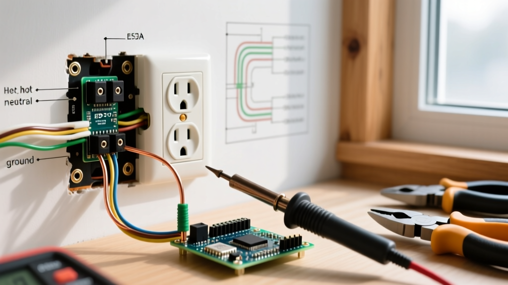
Locate your main service panel and switch the target breaker to the OFF position. If the breaker is unlabeled, use a process of elimination with a lamp plugged into the target outlet. Once off, insert a non-contact voltage tester (NCVT) into both the top and bottom slots of the receptacle.
Safety Warning: Never trust a breaker label blindly. Cross-fed circuits or shared neutrals in older homes can leave the neutral wire energized even when the hot leg is disconnected. Always verify with a contact multimeter set to AC Voltage after removing the faceplate.
Step 2: Extraction and Wire Assessment
Remove the center 6-32 faceplate screw. Remove the top and bottom mounting screws securing the receptacle yoke to the electrical box. Gently pull the device out, being mindful of the tight bending radius of 12 AWG Romex in shallow 2.5-inch deep boxes.
Inspect the existing wire insulation. If the PVC jacket is brittle, cracked, or shows signs of thermal degradation (browning near the terminals), you must cut back the damaged wire and strip a fresh section. If the wires are too short (less than 6 inches from the front of the box), NEC 300.14 requires you to install a pigtail extension using a wire nut or Wago 221 lever connector.
Step 3: Precision Wire Preparation
Proper strip length is critical to prevent arcing and ensure full terminal contact.
- For 14 AWG wire (15A circuits): Strip exactly 5/8 inch of insulation.
- For 12 AWG wire (20A circuits): Strip exactly 3/4 inch of insulation.
Use the gauge hole on your wire strippers. Do not use a knife to shave the insulation, as nicking the copper conductor creates a microscopic fracture point that will snap under the torque of the terminal screw.
Step 4: Termination Techniques (Screw vs. Back-Wire)
Modern commercial-grade receptacles (like the Leviton ProGrade line) offer two termination methods. Avoid the push-in 'backstab' holes entirely. Backstab connections rely on a small internal spring clip that loses tension over time due to thermal expansion and contraction, leading to high-resistance faults and melted yokes.
The Side-Wire Method:
- Form a J-hook in the stripped copper using the needle-nose pliers.
- Hook the wire around the terminal screw in a clockwise direction. This ensures that tightening the screw pulls the loop tighter rather than pushing it out.
- Ensure the insulation jacket butts right up against the washer head of the screw, but no bare copper is exposed outside the terminal plate.
The Back-Wire Clamp Method (Preferred for 12 AWG):
- Insert the straight, stripped wire into the back-wire hole located directly beneath the terminal screw.
- Tighten the screw. This drops an internal brass clamp that secures the wire with massive surface area contact, ideal for stiff 12 AWG wire.
Step 5: GFCI Specifics - Navigating LINE vs. LOAD
If you are installing a GFCI receptacle in a kitchen, bathroom, or exterior location, you must correctly identify the LINE and LOAD terminals. The LINE terminals receive incoming power from the panel. The LOAD terminals feed downstream standard outlets, extending ground-fault protection to them.
Most modern GFCIs (such as the Eaton GFTR series) feature a yellow warning tape covering the LOAD terminals. If you are only replacing a single outlet with no downstream devices, connect your hot and neutral wires only to the LINE terminals. Connecting incoming power to the LOAD terminals will result in a GFCI that trips immediately and refuses to reset.
Step 6: Torque Verification and Mounting
Under the latest NEC 110.14(D) requirements, terminations must be tightened to the manufacturer's specified torque. For almost all 15A and 20A residential receptacles, this is 14 inch-pounds. Set your torque screwdriver to 14 in-lbs, tighten the screw until the tool clicks, and stop. Overtightening can strip the brass threads or snap the screw head; undertightening causes resistive heating.
Fold the wires neatly into the back of the box using a 'Z' fold pattern. Secure the yoke to the box. Use a receptacle leveler or the built-in yoke leveling screws to ensure the faceplate will sit perfectly flush against the drywall.
Critical Failure Modes and Edge Cases
The Multi-Wire Branch Circuit (MWBC) Trap
If you are replacing a standard receptacle with a GFCI in an older home, you may encounter an MWBC (two hot wires sharing a single neutral). If you wire both hot legs and the shared neutral to the LOAD side of a GFCI, the opposing magnetic fields will cause an immediate, unresettable trip. Solution: GFCIs on MWBCs must be installed at the breaker panel (using a 2-pole GFCI breaker), or the shared neutral must be separated in the junction box, which often requires pulling new cable.
Tamper-Resistant (TR) Insertion Force
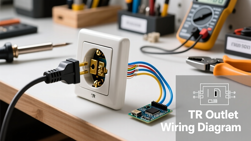
All 15A and 20A receptacles installed in dwelling units must be Tamper-Resistant. The internal shutters require equal, simultaneous pressure on both the hot and neutral blades to open. If you find a plug difficult to insert, do not force it or file down the plug blades. Ensure the plug blades are straight and push firmly and evenly. A drop of dielectric grease on the plug blades can ease insertion without compromising conductivity.
Authoritative References and Safety Standards
Electrical work is inherently dangerous and heavily regulated. Always consult local amendments to the national code before beginning work. The procedures outlined above align with the following authoritative standards:
- National Fire Protection Association (NFPA): For comprehensive details on NEC Article 210 (Branch Circuits) and Article 406 (Receptacles), refer to the NFPA 70 National Electrical Code.
- Consumer Product Safety Commission (CPSC): For statistical data on electrical fires and the life-saving importance of GFCI and AFCI integration, review the CPSC Electrical Safety Center.
- Occupational Safety and Health Administration (OSHA): For proper Lockout/Tagout (LOTO) procedures and workplace electrical safety verification, consult the OSHA Electrical Safety Guidelines.
By respecting the physical properties of the wire, adhering to precise torque specifications, and understanding the internal mechanics of modern TR and GFCI devices, you ensure a safe, code-compliant installation that will operate flawlessly for decades.