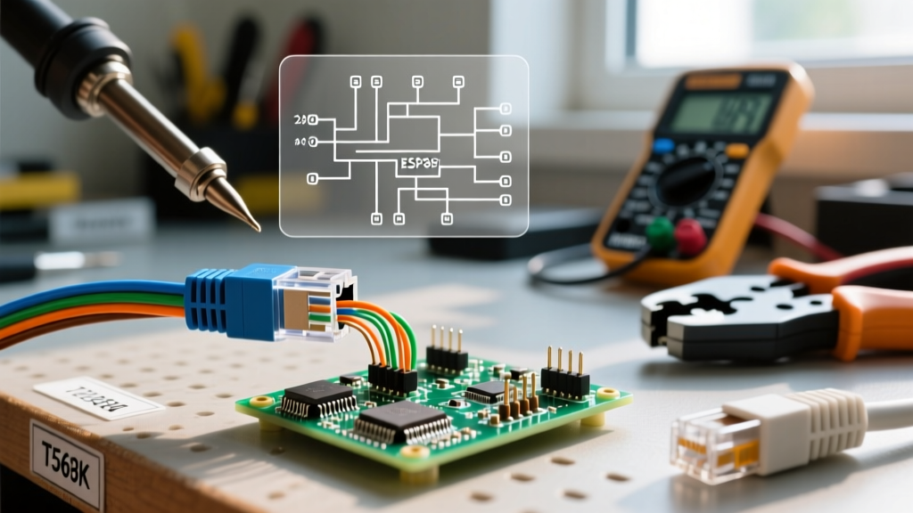

Introduction to Ethernet Termination Inspection
In the modern smart home and commercial enterprise landscape of 2026, structured cabling is the central nervous system of the building. While electricians and low-voltage technicians are adept at pulling Cat6 and Cat6A cables, the termination phase is where 90% of network faults originate. Inspecting a network drop requires more than a basic continuity tester; it requires a deep, practical understanding of the wiring diagram for ethernet plug terminations to isolate high-frequency faults, crosstalk, and Power over Ethernet (PoE) failures.
This inspection and testing guide provides field technicians, DIY enthusiasts, and quality assurance inspectors with a rigorous framework for evaluating RJ45 plug and keystone jack terminations. We will cover the ANSI/TIA-568.2-D standards, visual inspection metrics, wire mapping anomalies, and advanced certification troubleshooting.
The Core Standards: T568A vs. T568B Pinouts
Before testing any link, an inspector must verify which standard was deployed. The Telecommunications Industry Association (TIA) recognizes two primary pinout configurations for 8P8C (commonly called RJ45) modular plugs. While both standards perform identically from a data transmission standpoint, mixing them on the same cable creates a crossover link, which will cause link failures on older network interface cards.
Pinout Comparison Matrix
| Pin | T568A Color Code | T568B Color Code | Signal / Pair |
|---|---|---|---|
| 1 | White/Green | White/Orange | TX+ (Pair 3) |
| 2 | Green | Orange | TX- (Pair 3) |
| 3 | White/Orange | White/Green | RX+ (Pair 2) |
| 4 | Blue | Blue | Unused/PoE (Pair 1) |
| 5 | White/Blue | White/Blue | Unused/PoE (Pair 1) |
| 6 | Orange | Green | RX- (Pair 2) |
| 7 | White/Brown | White/Brown | Unused/PoE (Pair 4) |
| 8 | Brown | Brown | Unused/PoE (Pair 4) |
Note: As of 2026, T568A remains the mandated standard for US government and many new commercial builds, while T568B is heavily entrenched in legacy residential and enterprise retrofits. Always verify the site's master specification before condemning a termination.
Visual Inspection: The 13mm Untwist Rule
When using a wiring diagram for ethernet plug validation, visual inspection is your first line of defense against Near-End Crosstalk (NEXT). The twisting of the copper pairs is engineered to cancel out electromagnetic interference (EMI). When a technician strips the jacket and untwists the pairs to insert them into the plug channels, they compromise this cancellation.
- The 13mm Limit: According to BICSI guidelines and the ANSI/TIA-568.2-D standard, the maximum allowable untwisted length for Cat6 and Cat6A cables is 13mm (0.5 inches). If an inspector visually identifies untwisted pairs extending beyond this threshold to the back of the plug teeth, the termination must be flagged for rework.
- Jacket Intrusion: The outer cable jacket must extend fully into the rear of the RJ45 plug and sit beneath the strain relief crimp bar. If bare twisted pairs are exposed outside the rear of the plug, the connection lacks mechanical stability and will fail under tension.
- Flush Cut Verification: Using a magnification loupe, inspect the front of the plug. All eight conductors must be cut perfectly flush and reach the very end of the plug. If Pin 4 (Blue) falls short of the gold contact teeth, you have an 'Open' fault.
Testing Tools: Wire Mapping vs. Certification
A common mistake in field inspections is relying on a $15 continuity tester. These devices only verify DC continuity and cannot detect high-frequency wiring diagram errors. To properly inspect an ethernet plug, you must use a Wire Mapper or a Cable Certifier.
Tool Categories and 2026 Pricing
- Basic Wire Mappers (e.g., Klein Tools Scout Pro 3): Priced around $130, these tools send low-frequency signals to verify pin-to-pin continuity, check for shorts, and identify split pairs. They are essential for quick pass/fail inspections.
- Advanced Qualifiers (e.g., Fluke Networks MicroScanner PoE): Costing approximately $550, these devices verify the wiring diagram while also testing PoE voltage, switch port identification, and cable length via Time Domain Reflectometry (TDR).
- Level III Certifiers (e.g., Fluke DSX-8000): Enterprise-grade tools starting at $14,000+. These test the wiring diagram alongside Insertion Loss, Return Loss, and Alien Crosstalk up to 2000 MHz, ensuring the plug termination meets strict Cat6A channel specifications.
Troubleshooting Matrix: Diagram Faults and Test Results
When your wire mapper or certifier flags a failure, you must map the error back to the physical wiring diagram for ethernet plug terminations. Below is a diagnostic matrix for common field failures.
| Tester Error | Physical Wiring Diagram Fault | Inspection Action Required |
|---|---|---|
| Open | Conductor did not reach the gold pin contact; wire slipped out of the channel during crimping. | Re-crimp. Ensure flush cuts and verify the cable jacket is fully seated in the strain relief. |
| Short | Two adjacent conductors are touching, or the crimp bar pierced the insulation of two wires. | Cut off the plug. Inspect the cable for nicked insulation before re-terminating. |
| Reversed Pair | Tip and Ring of a single pair are swapped (e.g., Pin 1 is Green, Pin 2 is White/Green). | Check T568A/B color sequence. The technician swapped the solid and striped wires of a pair. |
| Split Pair | Wires are mapped 1-to-1 continuity, but not twisted together (e.g., Pins 3 & 6 use Blue/White-Blue instead of Orange/White-Orange). | Re-terminate using the correct diagram. This is the most common cause of unexplained gigabit speed drops. |
| Crossed Pair | A wire is placed in the wrong pin channel entirely (e.g., Pin 1 wired to Pin 3). | Verify the technician followed the exact T568A or T568B color sequence left-to-right. |
Edge Cases: PoE Type 4 and Shielded Plug Inspections
As Power over Ethernet scales to support high-draw devices like PTZ cameras and heavy-duty wireless access points, the physical inspection of the plug becomes a fire safety issue.
Inspector Warning: The IEEE 802.3bt (Type 4) standard delivers up to 90W of power. If a technician uses Copper Clad Aluminum (CCA) cable or a plug with undersized gold contacts, the termination point will overheat, melt the polycarbonate plug housing, and cause intermittent link drops. Always verify solid bare copper (23 AWG) during inspection.
Inspecting Shielded (F/UTP) Terminations
For industrial environments requiring shielded plugs, the wiring diagram extends beyond the 8 copper pins to include the drain wire and shield termination.
- Verify the drain wire is wrapped back over the cable jacket and makes 360-degree contact with the metal shell of the shielded RJ45 plug.
- Ensure the shielded plug's metal housing is properly crimped to establish a continuous ground path back to the patch panel.
- Test for ground loops using a multimeter; the shield should be grounded at the patch panel side, but testing continuity at the workstation side can verify the integrity of the drain wire connection at the plug.
Final Inspection Workflow Summary
A successful ethernet termination inspection in 2026 requires a methodical approach. First, confirm the site standard (T568A or T568B). Second, perform a visual inspection using a loupe to enforce the 13mm untwist rule and verify jacket intrusion. Third, connect a qualified wire mapper to detect split pairs and crossed pairs that basic testers miss. Finally, for PoE-heavy networks, inspect the physical integrity of the contacts to prevent thermal failure. By anchoring your testing workflow to the precise wiring diagram for ethernet plug configurations, you eliminate the vast majority of Layer 1 network faults before the system ever goes live.