
Diagnosing the Shock: Static Discharge vs. Electrical Fault
Getting shocked by an electrical outlet is a jarring experience that ranges from a harmless static discharge to a life-threatening ground fault. As homes age and electrical loads increase, receptacle degradation becomes a critical hazard. According to the National Fire Protection Association (NFPA), electrical receptacles are a leading point of failure in residential wiring systems. Before tearing into the drywall, it is imperative to differentiate between environmental static and a genuine wiring fault. Static shocks are high-voltage, low-current, and instantaneous. True electrical faults deliver sustained 120V or 240V alternating current, which can cause muscle tetany and ventricular fibrillation.
The Shock Diagnostic Matrix
Use the following matrix to triage the type of shock you are experiencing before proceeding to tool-based testing.
| Shock Type | Sensation & Duration | Root Cause | Danger Level |
|---|---|---|---|
| Static Discharge | Sharp snap, instantaneous, single event | Low humidity, synthetic carpets, triboelectric effect | Negligible |
| Capacitive Coupling | Tingling vibration, continuous while touching | Ungrounded metal faceplate near live conductors | Low (Microshock) |
| Ground Fault Leakage | Mild to severe tingle, localized to contact point | Degraded insulation, missing equipment ground | Moderate to High |
| Reverse Polarity / Hot-Ground | Severe muscle contraction, inability to let go | Swapped hot/neutral, energized ground path | Lethal (Macroshock) |
Essential Testing Arsenal for 2026
To properly investigate why you are being shocked by an electrical outlet, you must move beyond basic visual inspections. Professional diagnostics require specific, calibrated instruments. Here is the exact toolkit required for comprehensive receptacle testing:
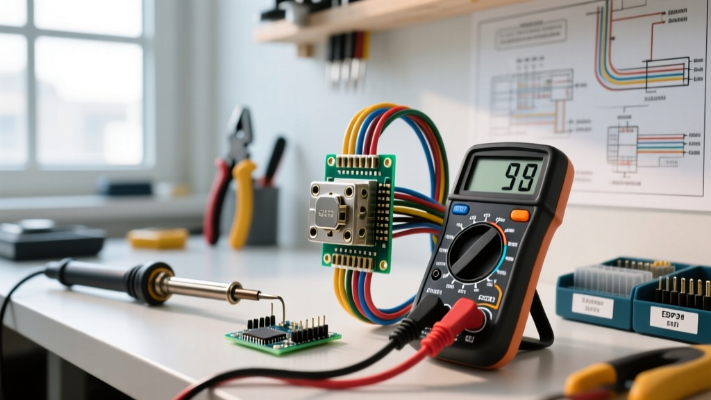
- Fluke 117 True-RMS Multimeter ($200 - $230): Features integrated VoltAlert non-contact voltage detection and low-impedance (LoZ) mode to eliminate ghost voltage readings.
- Klein Tools RT250 GFCI Receptacle Tester ($35 - $45): Tests standard wiring, GFCI trip functionality, and provides a clear LED matrix for polarity and ground faults.
- Amprobe AT-3500 Advanced Circuit Tracer ($150 - $170): Essential for tracking down shared neutrals and identifying the exact breaker tied to a miswired downstream circuit.
- Category 0 Arc Flash Gloves & Safety Glasses: As mandated by OSHA electrical safety guidelines, proper PPE is non-negotiable when testing live 120V/240V circuits.
The 4-Step Inspection and Testing Protocol
Follow this sequential protocol to isolate the exact failure mode causing the shock hazard.
Step 1: Thermal and Visual Triage
Before inserting any probes, perform a non-contact thermal scan. Loose connections at the terminal screws generate significant resistive heating. Using an infrared thermometer, scan the faceplate. A temperature delta of more than 15°F above ambient room temperature indicates a high-resistance connection or internal arcing. Next, remove the faceplate and inspect the receptacle yoke. Look for carbon tracking (black soot marks) or melted thermoplastic around the terminal screws. If present, the receptacle internals are compromised and must be replaced immediately.
Step 2: Polarity and Ground Verification
Insert the Klein RT250 into the top receptacle, then the bottom. A standard 'Correct' reading shows two amber lights. However, if you are experiencing shocks, look closely for the 'Hot/Neu Reverse' or 'Hot/Ground Reverse' indicators. Warning: A standard 3-light tester cannot detect a 'bootleg ground'—a dangerous jumper wire connecting the neutral and ground terminals behind the receptacle. To rule this out, you must proceed to Step 3.
Step 3: Ground Path Impedance and Bootleg Detection
Set your Fluke 117 to AC Voltage. Measure Hot-to-Neutral (H-N), Hot-to-Ground (H-G), and Neutral-to-Ground (N-G).
Expected Readings: H-N should be ~120V. H-G should be ~120V. N-G should be < 2V.
Fault Indication: If H-N is 120V but H-G is 0V, you have an open ground. If N-G reads 120V, the hot and ground wires are reversed. If the RT250 showed a correct ground but your multimeter shows an open ground, you have found a bootleg ground. This is a severe NEC violation that tricks testers while leaving the user exposed to shock if the neutral wire ever disconnects upstream.
Step 4: Leakage Current and GFCI Threshold Testing
If the wiring is correct but a mild tingling shock persists, the issue may be a failing appliance or a degraded GFCI mechanism. The Electrical Safety Foundation International (ESFI) notes that GFCIs are designed to trip at a leakage current threshold of 4 to 6 milliamps (mA). Use the test button on the RT250 to force a trip. If the GFCI fails to trip within 25 milliseconds, the internal solenoid is seized, and the device is providing zero shock protection despite having correct wiring.
Edge Cases: Why the Tester Says 'Correct' But You Still Get Shocked
When standard testing yields 'normal' results, but the user still reports getting shocked by an electrical outlet, you are likely dealing with one of three advanced edge cases:
- Shared Neutrals (Multi-Wire Branch Circuits): If a 120V circuit shares a neutral with another phase, and the handle-tied breaker is split or the neutral is broken downstream, the neutral wire can become energized at 120V. This will shock anyone touching a grounded appliance plugged into the receptacle.
- Induced Voltages from High-Voltage Proximity: Receptacles routed parallel to high-amperage feeders (like a 100A subpanel feed) can experience capacitive coupling. While a high-impedance digital multimeter might read 40V to 60V on the ground wire, the actual current capacity is negligible (microamps). Switching to the LoZ (Low Impedance) mode on the Fluke 117 will bleed off this ghost voltage, confirming it is harmless induction rather than a hard fault.
- Degraded Tamper-Resistant (TR) Shutters: In homes built after 2008, TR receptacles are code-mandated. If the internal plastic shutters crack, a user inserting a plug may inadvertently contact the live bus bar before the ground pin engages, resulting in a micro-shock.
Remediation and NEC Compliance
Once the fault is isolated, remediation must align with the latest National Electrical Code (NEC) standards. Under NEC Article 406.4(D), any replacement of a faulty receptacle in a location requiring GFCI protection must be upgraded to a GFCI receptacle, even if no equipment ground exists. When installing a GFCI on a 2-wire (ungrounded) system, you must apply the included 'No Equipment Ground' sticker to the faceplate. Furthermore, all 15A and 20A, 125V receptacles in dwelling units must be Tamper-Resistant (TR) per NEC Article 406.12. If the shock was caused by a broken equipment ground, do not simply replace the receptacle. You must either run a new equipment grounding conductor back to the panel or upgrade the entire circuit to include a proper ground. Relying on metallic conduit or armor cable (BX) as a ground path in older homes is highly unreliable due to internal corrosion and loose fittings, which dramatically increases ground impedance and prevents breakers from tripping during a fault.
Expert Insight: Never ignore a 'mild' tingle from an outlet. A 5mA shock feels like a tingle, but if the skin is wet or the contact area increases, the same fault can easily push 30mA through the body, crossing the threshold into respiratory paralysis. Always test, verify, and remediate immediately.