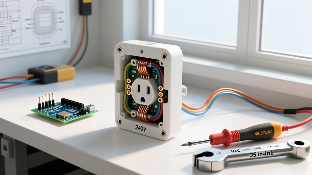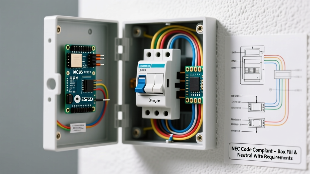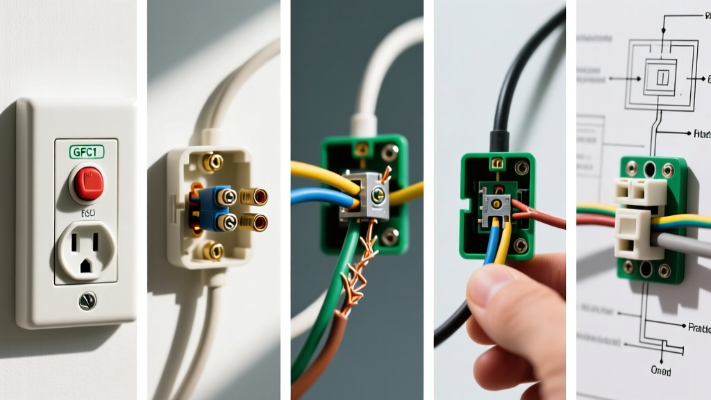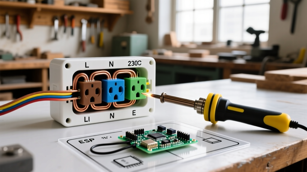

The Anatomy of an Electrical Plug: Terminal to Prong Mapping
Understanding electrical plug wiring colors is not merely an exercise in passing a municipal inspection; it is the foundational baseline for preventing arc faults, ensuring proper breaker tripping, and avoiding lethal electrical shocks. Whether you are wiring a standard NEMA 5-15 replacement plug for a power tool or terminating a 50-amp NEMA 14-50 receptacle for a Level 2 EV charger, the color-to-terminal mapping must be exact. In 2026, with the widespread adoption of AFCI/GFCI dual-function breakers and sensitive smart-home electronics, reversed polarity or improper grounding can cause nuisance tripping, equipment degradation, or severe fire hazards.
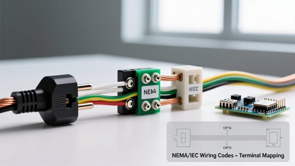
This wiring diagram reference breaks down the exact color codes, terminal screw assignments, and physical prong mappings for both North American (NEMA) and International (IEC) standards. We will also cover critical edge cases, such as multi-wire branch circuits (MWBC) and high-amperage 240V configurations.
North American (NEMA) Electrical Plug Wiring Colors
In the United States and Canada, the National Electrical Code (NEC) strictly dictates wire color identification under Articles 200 (Use and Identification of Grounded Conductors), 210 (Branch Circuits), and 250 (Grounding and Bonding). The physical design of NEMA plugs enforces these color codes through varied blade widths and terminal screw finishes.
Standard 120V Configurations (NEMA 1-15 and 5-15)
For standard 120V, 15-amp applications, the wiring color scheme is universally standardized across residential and commercial environments:
- Hot (Line): Black (or Red/Blue in some conduit runs). Connects to the Brass terminal screw and maps to the narrow vertical blade.
- Neutral (Grounded): White (or Grey). Connects to the Silver terminal screw and maps to the wide vertical blade.
- Ground (Equipment Grounding Conductor): Green, Green with Yellow Stripe, or Bare Copper. Connects to the Green terminal screw and maps to the U-shaped or round pin.
Expert Note: Never use the push-in 'backstab' terminals on 12 AWG wire. While NEC allows them for 14 AWG, the spring-tension contacts often fail under continuous 15A+ loads, leading to thermal melting. Always use the side-screw terminals or the back-wire clamp plates found on commercial-grade plugs (e.g., Leviton 5266-C or Hubbell 5266).
240V and High-Amperage Configurations (NEMA 6 and 14 Series)
When stepping up to 240V for appliances, welders, or EVSE (Electric Vehicle Supply Equipment), the neutral wire is sometimes omitted, and a second hot leg is introduced.
- NEMA 6-15 / 6-20 (240V, No Neutral): Uses two Hot wires (Black and Red) and one Ground (Green/Bare). There is no Silver terminal. Both blade terminals are Brass.
- NEMA 14-30 / 14-50 (120/240V, With Neutral): Uses two Hots (Black, Red), one Neutral (White), and one Ground (Green/Bare). This is the standard for modern electric dryers, ranges, and 50-amp RV/EV receptacles.
Comprehensive NEMA Plug Wiring Color Matrix
The following table serves as a quick-reference diagram matrix for the most common NEMA plug configurations encountered in residential and light-commercial wiring.
| NEMA Type | Voltage | Amperage | Hot Wire(s) | Neutral Wire | Ground Wire | Terminal Screw Colors |
|---|---|---|---|---|---|---|
| 5-15P | 125V | 15A | Black | White | Green/Bare | Brass, Silver, Green |
| 5-20P | 125V | 20A | Black | White | Green/Bare | Brass, Silver, Green |
| 6-15P | 250V | 15A | Black, Red | None | Green/Bare | Brass (x2), Green |
| 6-50P | 250V | 50A | Black, Red | None | Green/Bare | Brass (x2), Green |
| 14-30P | 125/250V | 30A | Black, Red | White | Green/Bare | Brass (x2), Silver, Green |
| 14-50P | 125/250V | 50A | Black, Red | White | Green/Bare | Brass (x2), Silver, Green |
International (IEC) Wiring Color Standards
If you are wiring equipment for export, working on imported machinery, or dealing with IEC 60309 industrial pin-and-sleeve connectors, the North American color code does not apply. The International Electrotechnical Commission (IEC 60445) standardizes plug wiring colors across the UK, EU, Australia, and most of the globe.
- Line (Hot): Brown (L1), Black (L2), Grey (L3) for three-phase.
- Neutral: Blue.
- Earth (Ground): Green with a Yellow stripe (always).
Warning for Import/Export Equipment: Never assume a blue wire is neutral in a legacy US installation. Prior to the 1970s, some US control circuits used blue for DC or switched AC. Always verify with a Fluke 117 True-RMS multimeter before terminating IEC-colored wires into a North American panel or plug.
Critical Wiring Diagram Reference: Step-by-Step Termination
For a standard NEMA 5-15P replacement plug (e.g., Leviton 00R-5266-C00), follow this precise termination sequence to ensure mechanical stability and code compliance:
- Strip the Jacket: Remove exactly 2 inches of the outer PVC jacket. Do not nick the inner wire insulation.
- Strip the Conductors: Strip 3/4 inch of insulation from the Black, White, and Green wires using a precision wire stripper (e.g., Klein Tools 11063W).
- Form the J-Hook: Bend the exposed copper clockwise into a tight 'J' hook using needle-nose pliers. The clockwise bend ensures the screw pulls the wire tighter as it is torqued down.
- Terminate Ground First: Loop the Green/Bare wire around the Green screw. Tighten to roughly 14 inch-pounds. Tug firmly to verify.
- Terminate Neutral: Loop the White wire around the Silver screw. Ensure no bare copper is exposed outside the screw head (a common NEC violation that can cause short circuits in the plug housing).
- Terminate Hot: Loop the Black wire around the Brass screw.
- Secure the Cord Grip: The internal cord clamp must grip the outer PVC jacket, never the individual inner wires. This prevents strain from pulling the wires off the terminal screws.
Edge Cases, Failure Modes, and Troubleshooting
Reversed Polarity and Bootleg Grounds
Reversed polarity occurs when the Black (Hot) and White (Neutral) wires are swapped on the plug terminals. While the device may still power on, the internal switch of the appliance will only break the neutral path, leaving the internal components energized at 120V even when turned off. The Occupational Safety and Health Administration (OSHA) frequently cites reversed polarity in workplace tool inspections as a severe shock hazard.
A 'bootleg ground' is an illegal and highly dangerous workaround where a jumper wire is installed between the Neutral (Silver) terminal and the Ground (Green) terminal on a 2-prong to 3-prong adapter or replacement plug. If the neutral wire breaks upstream, the entire metal chassis of the connected appliance becomes energized at 120V. Always test newly wired plugs with a dedicated receptacle tester like the Klein Tools RT210 to verify correct wiring and ground integrity.
Multi-Wire Branch Circuits (MWBC) on 240V Plugs
When wiring a NEMA 14-30 or 14-50 plug for an appliance on a Multi-Wire Branch Circuit, the two hot legs (Black and Red) must be on opposite phases (240V across them). If they are mistakenly placed on the same phase (0V across them, 120V to neutral), the shared neutral wire will carry the sum of both currents rather than the difference, instantly overloading the neutral conductor and creating a severe fire hazard. Always measure phase-to-phase voltage with a multimeter before connecting the plug to the equipment.
Authoritative References & Code Compliance
Electrical work must always comply with local jurisdictions and the latest adopted edition of the National Electrical Code. For further reading on safety standards and plug configurations, consult the following authoritative resources:
- National Fire Protection Association (NFPA): Review the latest NEC guidelines on conductor identification and grounding at the NFPA NEC Portal.
- Occupational Safety and Health Administration (OSHA): Refer to OSHA's Electrical Safety Standards for workplace wiring and flexible cord compliance.
- U.S. Consumer Product Safety Commission (CPSC): Access consumer guides on preventing electrical fires and proper cord maintenance via the CPSC Electrical Safety Center.