
The Critical Importance of 120 Volt Outlet Testing
Testing a 120 volt electrical outlet is not just about verifying that power is present; it is a critical diagnostic procedure to ensure the safety of your home or facility and the longevity of connected appliances. According to the U.S. Consumer Product Safety Commission, faulty receptacles and degraded wiring connections are leading contributors to residential electrical fires. A receptacle that reads 120V on a basic tester might still harbor dangerous hidden faults, such as a floating neutral, a bootleg ground, or high-resistance backstabbed connections that can melt under load.
In this comprehensive inspection guide, we move beyond simple plug-in testers. We will cover precision multimeter diagnostics, voltage tolerance standards, and advanced troubleshooting matrices to identify edge cases that generic guides miss. Whether you are inspecting a newly installed 15-amp duplex receptacle or troubleshooting a vintage 20-amp kitchen circuit, this protocol ensures your 120 volt electrical outlet meets modern safety benchmarks.
Essential Diagnostic Tools for Receptacle Inspection
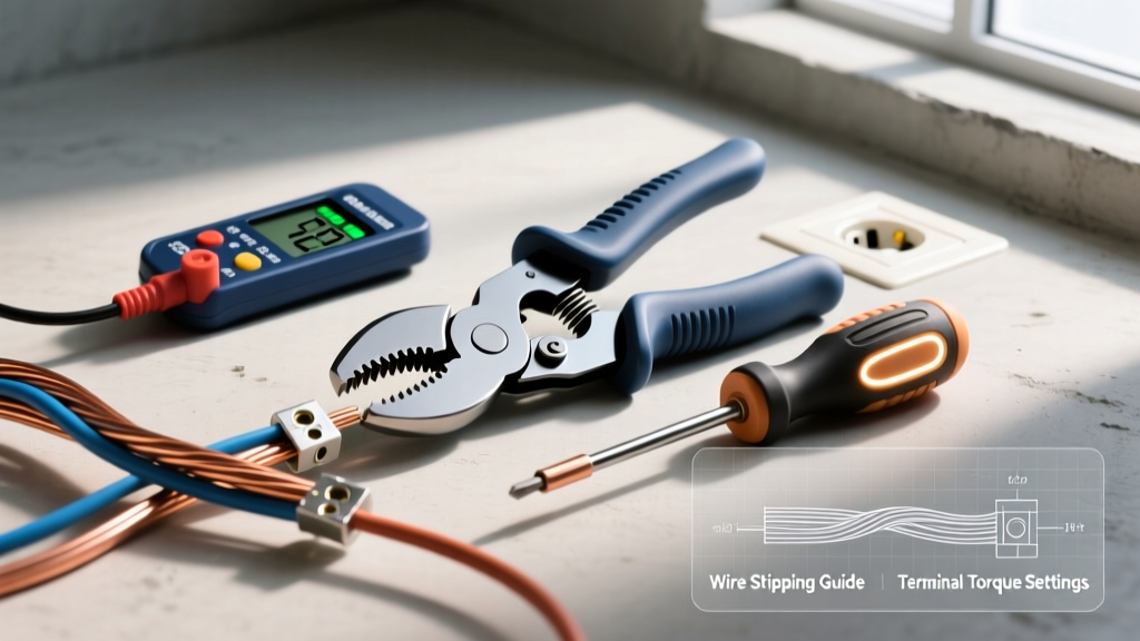
Professional electrical inspection requires a tiered approach. Relying on a single tool leaves blind spots in your diagnostic process. Here are the specific instruments required for a thorough 120 volt electrical outlet evaluation in 2026:
- Tier 1: GFCI Receptacle Tester (e.g., Klein Tools RT250) - Priced around $28, this tool provides a rapid visual check of standard wiring configurations and includes a dedicated button to trip GFCI circuits.
- Tier 2: True RMS Digital Multimeter (e.g., Fluke 117) - Retailing between $200 and $220, a True RMS meter is non-negotiable for measuring non-linear loads and detecting subtle voltage drops that average-responding meters miss.
- Tier 3: Advanced Circuit Analyzer (e.g., Amprobe INSP-3) - At approximately $150, this device detects 'bootleg grounds' and measures exact ground impedance, which standard 3-light testers cannot do.
Safety Warning: Before inserting any probes or testers, visually inspect the receptacle face. Look for scorch marks, cracked thermoplastic faces, or loose-fitting plug blades. The Occupational Safety and Health Administration (OSHA) mandates that any receptacle showing physical thermal damage must be de-energized and replaced immediately, as internal arc faults may be present.
Phase 1: Rapid Visual and Plug-In Tester Inspection
The first step in evaluating a 120 volt electrical outlet is the rapid plug-in test. Insert your Klein Tools RT250 or equivalent tester into the receptacle. Observe the LED indicator pattern and cross-reference it with the diagnostic table below.
| LED Pattern (Right / Center / Left) | Indicated Condition | Required Action |
|---|---|---|
| ON / OFF / ON | Correct Wiring | Proceed to Phase 2 multimeter testing. |
| OFF / ON / ON | Reverse Polarity (Hot/Neutral Swapped) | De-energize circuit and swap brass/nickel screw wires. |
| ON / ON / OFF | Missing Equipment Ground | Check panel ground bar; verify bare copper wire at receptacle. |
| OFF / ON / OFF | Missing Neutral / Hot Wire on Neutral | Inspect neutral bus bar and side-wire nickel screw connection. |
| ON / OFF / OFF | Hot Wire on Ground / Missing Neutral | Immediate hazard. Shut off breaker and trace circuit wiring. |
Note: While a 3-light tester is excellent for catching gross wiring errors, it will falsely read 'Correct Wiring' if a previous electrician installed a 'bootleg ground' (a jumper wire connecting the neutral terminal to the ground terminal). Only Phase 2 and Phase 3 testing will reveal this severe code violation.
Phase 2: Precision Multimeter Diagnostics
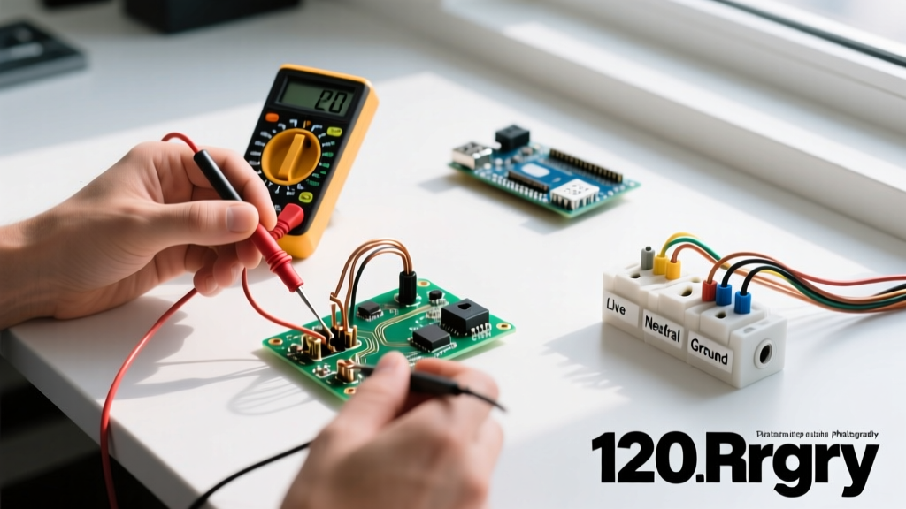
To verify the true health of the 120 volt electrical outlet, you must measure the voltage differentials across three specific pin combinations. Set your Fluke 117 to AC Voltage (V~) and insert the probes into the receptacle slots.
1. Hot to Neutral (H-N)
Insert the red probe into the shorter (hot) slot and the black probe into the longer (neutral) slot. Under the ANSI C84.1 standard, the nominal 120V supply must fall within Range A tolerances: 114V to 126V. If your reading is below 114V, you are experiencing excessive voltage drop, likely due to undersized wire (e.g., 14 AWG on a long 15-amp run) or a loose connection upstream.
2. Hot to Ground (H-G)
Insert the red probe into the hot slot and the black probe into the round ground hole. This reading should be nearly identical to your H-N reading, or slightly higher (by 0.5V to 1.5V). Critical Diagnostic Insight: If your H-G reading is significantly lower than your H-N reading, your hot and neutral wires are reversed at the receptacle or upstream. The ground is acting as the return path, which is a lethal shock hazard.
3. Neutral to Ground (N-G)
Insert the probes into the neutral slot and ground hole. This reading should be as close to 0V as possible, typically between 0.1V and 1.5V. This small voltage represents the natural voltage drop across the neutral wire due to current flow. If your N-G reading exceeds 2.0V, it indicates a loose neutral connection, an overloaded shared neutral (multi-wire branch circuit), or undersized wiring. High N-G voltage can cause sensitive electronics to malfunction and creates a shock risk if the ground path is broken.
Advanced Troubleshooting Matrix for 120V Outlets
When your multimeter readings deviate from the ANSI C84.1 standards, use this matrix to pinpoint the exact failure mode within the branch circuit.
| Symptom / Reading | Probable Root Cause | Expert Resolution |
|---|---|---|
| H-N reads 60V - 90V | Phantom voltage or high-resistance backstabbed connection. | Remove push-in backstabbed wires. Strip insulation and terminate using the side screw terminals with a proper J-hook. |
| H-N reads 120V, but drops to 95V under load | Loose upstream splice or corroded breaker terminal. | Plug in a 1500W space heater. Measure voltage at the panel and outlet. Tighten breaker lugs to 35 in-lbs and inspect wire nuts. |
| N-G reads 5V or higher | Shared neutral overload or floating neutral on MWBC. | Verify multi-wire branch circuit breakers are tied together. Check for broken neutral pigtails in upstream junction boxes. |
| Tester shows 'Correct' but N-G reads 120V | Bootleg ground (Neutral jumpered to Ground). | Remove the illegal jumper wire. Run a new dedicated equipment grounding conductor back to the panel if no ground exists. |
Navigating NEC Code Requirements and AFCI/GFCI Nuances
When inspecting a 120 volt electrical outlet, physical wiring is only half the battle. You must also verify compliance with the latest NFPA 70 National Electrical Code (NEC). As of the 2023 and upcoming 2026 NEC cycles, the requirements for ground-fault and arc-fault protection have expanded dramatically.
Pro-Tip: Testing AFCI ReceptaclesStandard plug-in GFCI testers will not reliably trip an Arc-Fault Circuit Interrupter (AFCI) receptacle or breaker unless the circuit has a true equipment ground. If you are testing an older 2-wire system where an AFCI breaker was installed for safety compliance, you must use the physical 'Test' button on the breaker or receptacle itself, or utilize a specialized AFCI test adapter that injects a high-frequency arc signature into the line.
GFCI Testing Protocols
For kitchens, bathrooms, garages, and outdoor 120 volt electrical outlets, GFCI protection is mandatory. When using a plug-in tester to trip a GFCI, note that the tester routes a small current from the hot wire to the ground wire to simulate a fault. If the receptacle lacks an equipment ground (common in pre-1960s homes), the plug-in tester's 'Test' button will do nothing. However, the GFCI's internal test button will still work, as it tests the internal circuitry by routing current from hot to neutral. If a GFCI is installed on an ungrounded circuit, it must be labeled 'No Equipment Ground' and 'GFCI Protected' per NEC 406.4(D)(2)(c).
Physical Receptacle Inspection: Beyond the Voltage
A 120 volt electrical outlet can have perfect voltage readings but still be a severe fire hazard due to mechanical degradation. Perform these physical inspections:
- Blade Retention Test: Insert a standard 15-amp plug into the receptacle. It should require firm pressure to insert and extract. If the plug slides in easily or falls out under the weight of its own cord, the internal brass contacts are fatigued. This causes arcing and high heat. Replace the receptacle immediately.
- Terminal Screw Inspection: Remove the receptacle from the box (with power OFF). Inspect the brass and nickel terminal screws. The wire should be looped clockwise around the screw so that tightening the screw pulls the loop closed. Ensure no bare copper is exposed outside the terminal plate, and that the insulation is not pinched under the screw head.
- Box Fill and Heat Dissipation: Verify that the electrical box is not overfilled. Cramming too many wires into a standard single-gang box traps heat generated by the receptacle and connected devices, accelerating the degradation of the thermoplastic housing.
Summary of Best Practices
Properly testing a 120 volt electrical outlet requires a methodical approach that combines rapid visual checks, plug-in pattern recognition, and precision multimeter diagnostics. By understanding the relationship between Hot, Neutral, and Ground voltages, and by recognizing the limitations of basic testers, you can identify dangerous edge cases like bootleg grounds and floating neutrals. Always adhere to current NEC standards, prioritize side-wiring over push-in backstabs, and replace any receptacle that exhibits mechanical wear or thermal damage. Safe, reliable power delivery starts at the point of connection.