
Understanding the "220V" Nomenclature in Modern Electrical Codes
When professionals and DIYers search for an electrical wiring 220v outlet diagram, they are typically looking to install a high-amperage receptacle for heavy-duty appliances, workshop machinery, or Level 2 Electric Vehicle (EV) chargers. However, from a strict electrical engineering and National Electrical Code (NEC) perspective, residential split-phase power in North America delivers 240 volts, not 220. The terms 220V, 230V, and 240V are often used interchangeably in colloquial settings, but modern receptacles, breakers, and NEC Article 210 guidelines are rated and tested at 240V.
As of 2026, the surge in residential EV charging stations and high-efficiency heat pumps has made 240V receptacle installations more common than ever. According to the U.S. Department of Energy, over 80% of modern home EV charging setups rely on a dedicated 240V circuit, making a firm grasp of these wiring diagrams essential for safety and code compliance.
CRITICAL SAFETY WARNING: Working inside a main service panel or subpanel exposes you to lethal voltage levels. Always de-energize the circuit at the main breaker, verify zero energy with a True-RMS multimeter (e.g., Fluke 117), and adhere strictly to NFPA 70E arc flash safety protocols. If you are not a licensed electrician, consult your local Authority Having Jurisdiction (AHJ) regarding permit requirements for high-amperage branch circuits.
NEMA Receptacle Configuration Matrix
The National Electrical Manufacturers Association (NEMA) dictates the physical blade configurations for high-voltage outlets. Choosing the correct configuration depends entirely on the load's amperage draw and whether the device requires a neutral wire (for 120V auxiliary electronics like timers or digital displays).
| NEMA Config | Poles / Wires | Voltage | Amperage | Common Applications (2026 Standards) |
|---|---|---|---|---|
| 6-15R | 2P / 3W (No Neutral) | 250V | 15A | Small window AC units, baseboard heaters |
| 6-20R | 2P / 3W (No Neutral) | 250V | 20A | Shop tools (TIG welders, air compressors) |
| 14-30R | 3P / 4W (With Neutral) | 125/250V | 30A | Electric dryers, portable generators |
| 14-50R | 3P / 4W (With Neutral) | 125/250V | 50A | Level 2 EV chargers, RV hookups, electric ranges |
Wire Sizing, Breaker Matching, and Conduit Fill
An accurate electrical wiring diagram is useless if the conductor ampacity does not match the overcurrent protection device (OCPD). The National Fire Protection Association (NFPA) outlines strict ampacity tables in NEC Chapter 9. Below is the reference chart for copper conductors (THHN/THWN-2) in standard residential environments.
| Breaker Size | Min. Copper AWG | Max Continuous Load (80% Rule) | Recommended Conduit (EMT) |
|---|---|---|---|
| 20A (2-Pole) | 12 AWG | 16A (3,840W) | 1/2 inch |
| 30A (2-Pole) | 10 AWG | 24A (5,760W) | 1/2 inch |
| 40A (2-Pole) | 8 AWG | 32A (7,680W) | 3/4 inch |
| 50A (2-Pole) | 6 AWG | 40A (9,600W) | 3/4 inch |
Pro-Tip for Long Runs: If your circuit run exceeds 100 feet from the subpanel to the receptacle, you must calculate voltage drop. For a 50A NEMA 14-50R EV charger located 150 feet from the breaker, upsizing from 6 AWG to 4 AWG copper is mandatory to keep voltage drop below the NEC-recommended 3% threshold.
Diagram Breakdown: Wiring a NEMA 14-50R (4-Wire 50A)
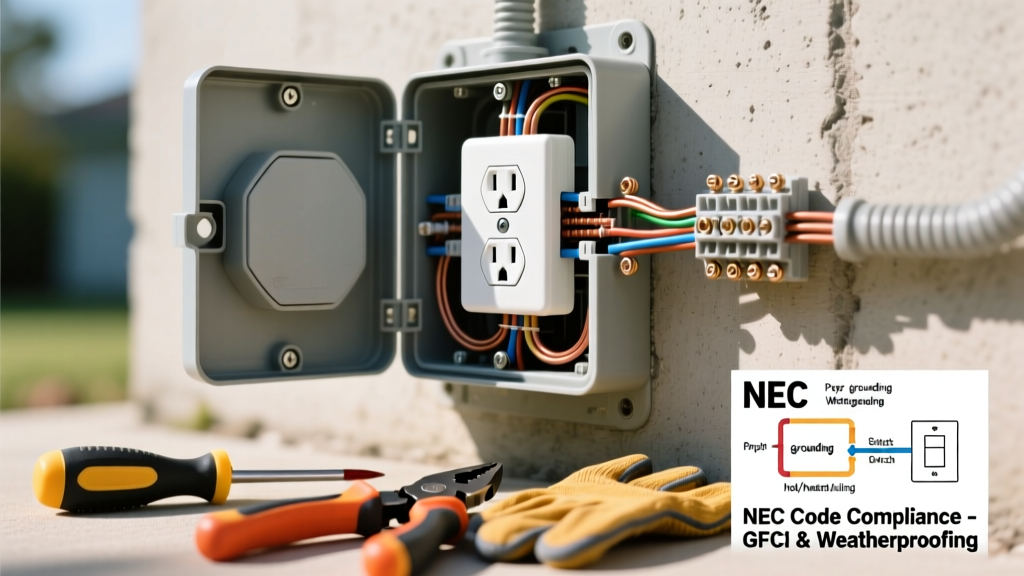
The NEMA 14-50R is the undisputed standard for modern high-draw residential applications. Unlike older 3-wire setups (which illegally bonded neutral and ground at the receptacle), modern NEC Article 250.140 strictly requires a dedicated 4-wire feed: two hot legs, one neutral, and one equipment grounding conductor (EGC).
Terminal Mapping and Color Coding
When looking at the back of a Leviton 279-S00 or Hubbell 9450A receptacle, you will identify four distinct termination points:
- X (Hot 1): Connects to the Black wire (Line 1 from Breaker Pole A).
- Y (Hot 2): Connects to the Red wire (Line 2 from Breaker Pole B).
- W (Neutral): Connects to the White wire (Grounded conductor from the panel's neutral busbar).
- G (Ground): Connects to the Bare or Green wire (EGC from the panel's grounding busbar).
Step-by-Step Termination and Torque Specifications
The Electrical Safety Foundation International (ESFI) reports that loose connections are a leading cause of residential electrical fires. High-amperage 240V circuits generate significant heat; therefore, precise wire preparation and torque application are non-negotiable.
- Strip the Jacket: Remove exactly 3/4 inch of insulation from 10-12 AWG wires, or 1 inch for 6-8 AWG wires. Do not nick the copper conductor, which creates a microscopic fracture point that will fail under thermal expansion.
- Dress the Wires: Form the conductors into neat, 90-degree bends inside the deep-gang box. Do not force or cramp the wires, as this can loosen terminal screws over time.
- Mechanical Lugs vs. Screw Terminals: For 50A receptacles, wires terminate into mechanical lugs. Insert the bare wire fully until the insulation touches the lug barrel. Tighten the set screw using a calibrated torque screwdriver (such as the Klein Tools 61036).
- Apply Exact Torque: Check the manufacturer's spec sheet on the device. Most 50A mechanical lugs require 75 in-lbs of torque, while standard 20A/30A screw terminals require 14 to 18 in-lbs. Under-torquing causes arcing; over-torquing strips the threads and crushes the copper strands.
- Secure the Yoke: Mount the receptacle to the box using the provided 6-32 or 8-32 machine screws. Ensure the yoke sits flush against the drywall or mud ring to prevent the faceplate from cracking when a heavy EV charging cable is plugged in.
Post-Installation Testing Protocol
Never energize a newly wired 240V circuit without performing a systematic validation sequence. Set your True-RMS multimeter to AC Voltage (V~) and execute the following measurements at the receptacle face:
- L1 to L2 (X to Y): Must read between 238V and 242V. (Confirms both breaker poles are live and phased correctly).
- L1 to Ground (X to G): Must read ~120V.
- L2 to Ground (Y to G): Must read ~120V.
- Neutral to Ground (W to G): Must read less than 2.0V. If you read 120V here, you have a catastrophic wiring error (likely a swapped neutral and hot wire), or an open neutral condition. Do not plug in any equipment until resolved.
Common Edge Cases & Failure Modes
Even with a perfect diagram reference, field conditions introduce variables that can compromise a 220V/240V outlet installation:
1. The "Backstab" Temptation
Never use push-in (backstab) spring terminals for any 240V load. While some 20A commercial receptacles feature push-in terminations, the spring tension degrades under the high thermal cycling of heavy loads like welders or EV chargers. Always use the side screw terminals or mechanical lugs.
2. Shared Neutrals in Multi-Wire Branch Circuits (MWBC)
If you are pulling wire for a subpanel or multiple 120V/240V devices, never share a neutral wire between independent circuits unless they are part of a properly configured MWBC with a simultaneous disconnect (handle-tied 2-pole breaker). A shared neutral on independent single-pole breakers can cause the neutral wire to carry the sum of the currents, leading to an immediate meltdown and fire hazard.
3. Aluminum Wire Oxidation
If your home was built in the 1970s or you are using modern AA-8000 series aluminum SER cable for a 50A run to save on copper costs, you must apply an antioxidant compound (like Noalox) to the wire strands before inserting them into mechanical lugs. Aluminum oxidizes rapidly when exposed to air, creating a high-resistance layer that generates extreme heat at the termination point.
By adhering strictly to these diagram references, torque specifications, and NEC guidelines, you ensure that your high-voltage receptacle installation is not only functional but inherently safe for decades of continuous use.