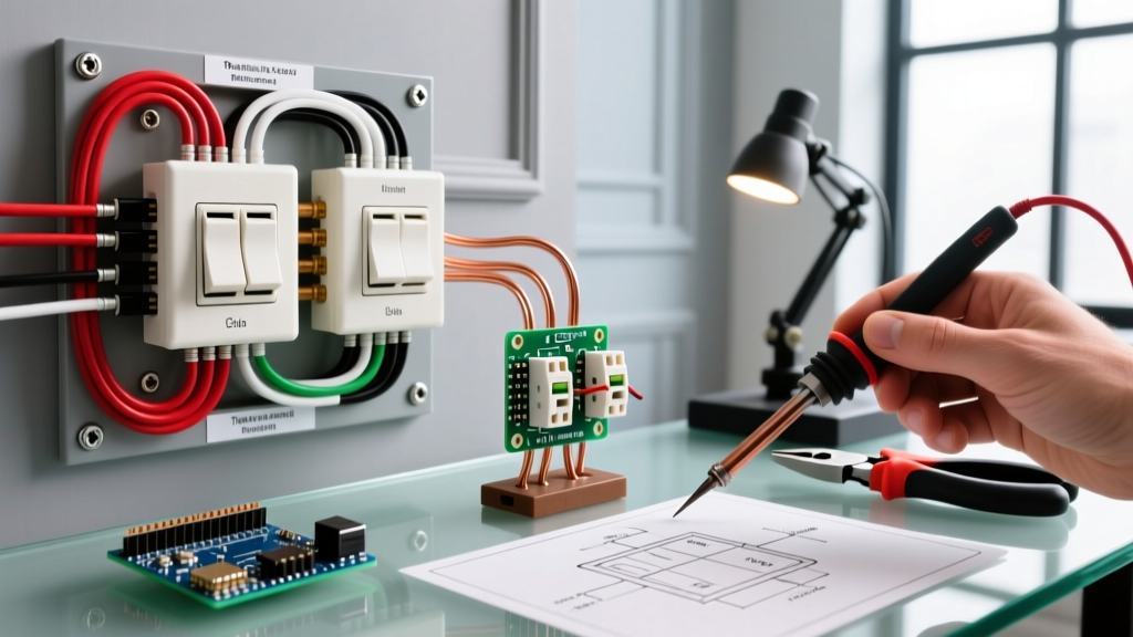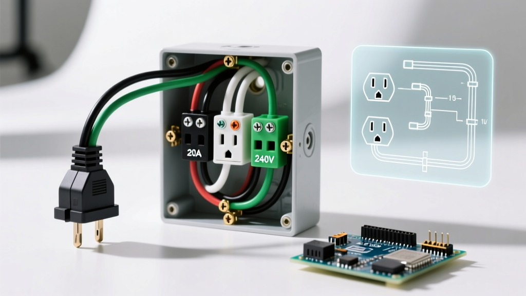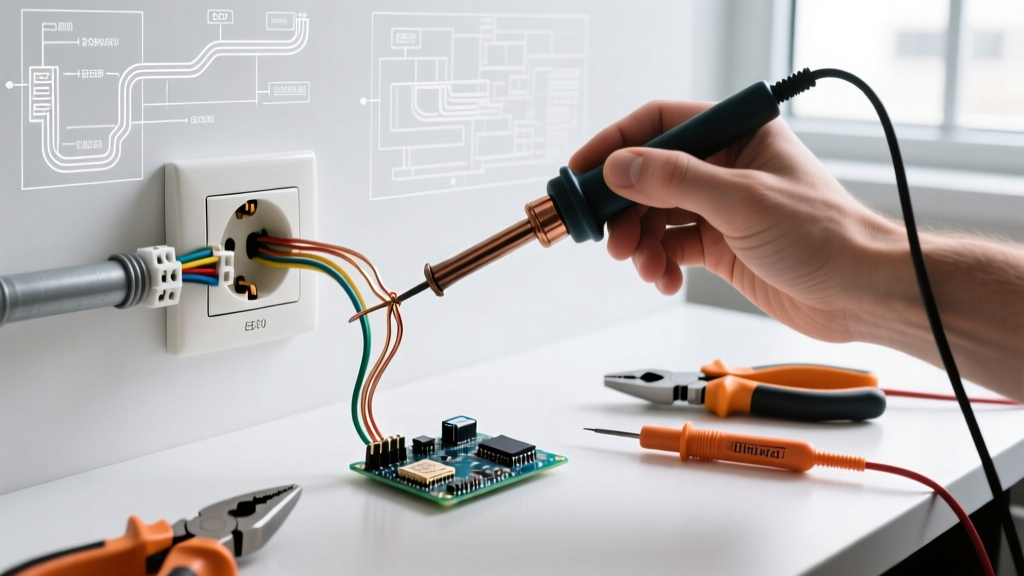

Routing power from an existing receptacle to control a new or existing lighting fixture is one of the most common residential electrical upgrades. However, the transition from a simple receptacle to a switched circuit introduces strict National Electrical Code (NEC) requirements that most outdated online tutorials completely ignore. If you are planning an electrical outlet to light switch conversion or addition in 2026, you must account for the mandatory neutral-at-the-switch rule, precise box fill calculations, and tamper-resistant mandates.
This comprehensive tool and material guide strips away the fluff and provides the exact Bill of Materials (BOM), professional-grade hand tools, and code-compliant workflows required to execute this project safely and legally.
The Bill of Materials (BOM): Wire, Boxes, and Connectors
The most critical mistake DIYers make when wiring an electrical outlet to a light switch is assuming a standard 14/2 NM-B (Romex) cable is sufficient for the switch leg. Under current NEC Article 404.2(C), a neutral conductor must be present at the switch box to accommodate smart switches, timers, and dimmers. Therefore, if power originates at the receptacle and you are running a new cable to the switch, you must use a 3-wire cable to provide a constant hot, a neutral, and a switched hot return.
| Component | Specification / Model | Est. Cost (2026) | NEC / Code Note |
|---|---|---|---|
| Switch Leg Cable | Southwire 14/3 NM-B (250ft coil) | $118.00 | Required to route hot, neutral, and switched hot. |
| New Switch Box | Carlon B618R (Single Gang, 18 cu in) | $1.45 | Min 16 cu in required; 18 cu in allows for bending radius. |
| Connectors | Wago 221-413 Lever Nuts (3-Port) | $0.68 / ea | UL Listed, reusable, transparent for visual wire seating. |
| Receptacle | Leviton T5325-W (Tamper Resistant) | $3.85 | NEC 406.12 mandates TR receptacles in all dwelling units. |
| Switch / Dimmer | Lutron DVRP-250P (Smart/Dimmer Ready) | $29.50 | Requires neutral connection; 14/3 cable provides this. |
Essential Hand Tools for the Job
Working inside an existing energized panel or junction box demands precision and verified safety equipment. Skip the bargain-bin tools; the following are industry-standard items that ensure clean terminations and prevent arc faults.
- Non-Contact Voltage Tester (NCVT): Fluke 1AC-II VoltAlert (~$38.00). While an NCVT is only your first line of defense, the Fluke 1AC-II features a continuous self-test function and a bright LED indicator, reducing the risk of false negatives compared to budget models.
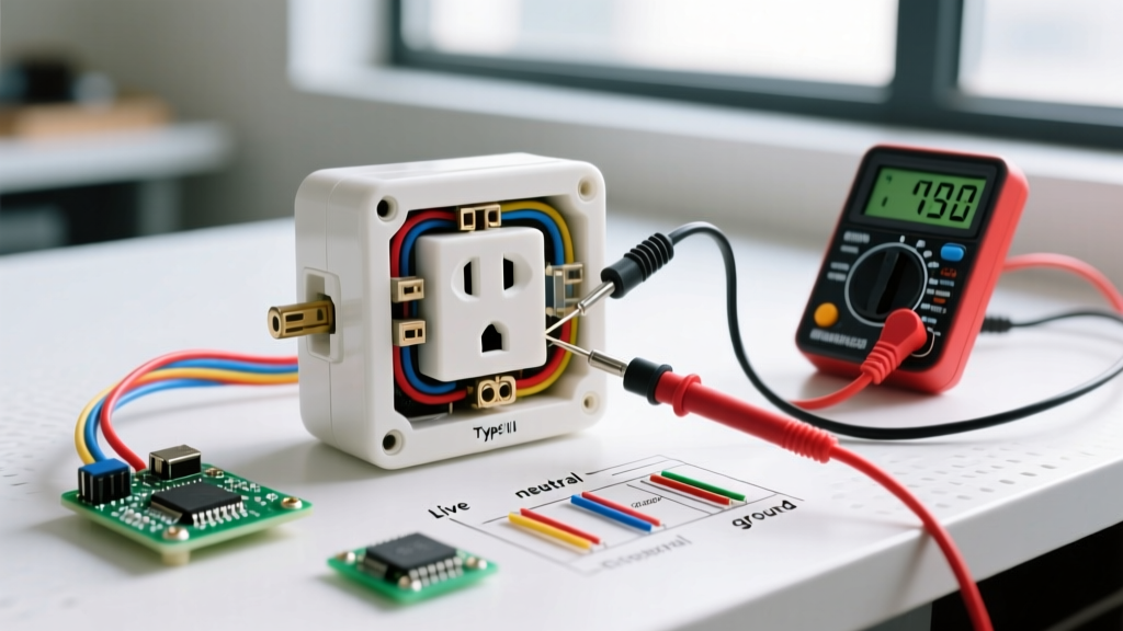
- Digital Multimeter (DMM): Klein Tools MM400 True-RMS (~$48.00). You must verify zero potential between hot, neutral, and ground before touching any bare copper. An NCVT cannot detect a floating neutral or a backfed circuit.
- Wire Strippers: Klein Tools 11055 (10-20 AWG Solid Wire Stripper) (~$29.00). The 11055 features precision-machined stripping holes that score the insulation without nicking the copper conductor. Nicked 14 AWG wire creates a localized hot spot and a potential failure point under load.
- Insulated Screwdrivers: Wiha 74401 Insulated Slotted/Phillips Set (~$32.00). Rated for 1000V, these provide a critical dielectric barrier if your tool accidentally bridges a terminal while working near adjacent live circuits in a multi-gang box.
Critical Code Alert: The NEC Neutral Mandate
NEC Article 404.2(C) - Switches Controlling Lighting Loads: 'Where switches control lighting loads, the grounded (neutral) circuit conductor shall be provided at the switch location.' - NFPA 70 (National Electrical Code)
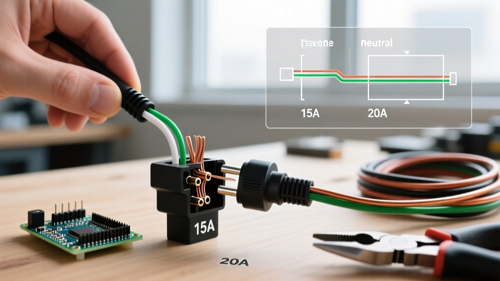
When pulling a switch leg from an electrical outlet, the power source (hot and neutral) is at the receptacle box. To comply with the code above, you must run 14/3 NM-B (or 12/3 if on a 20A circuit) to the new switch box.
How to Wire the 14/3 Switch Leg:
- Black Wire: Connects to the constant hot at the receptacle and lands on the 'Line' or 'Common' terminal at the switch.
- White Wire: Connects to the neutral bundle at the receptacle and lands on the 'Neutral' terminal at the switch (essential for smart switches).
- Red Wire: Connects to the 'Load' terminal at the switch and routes back to the receptacle box (or directly to the light fixture) to serve as the switched hot.
Warning: Older guides frequently instruct DIYers to use 14/2 NM-B and re-identify the white wire as a hot conductor. While this was permissible decades ago, doing so today leaves the switch box without a neutral, resulting in an immediate code violation and preventing the installation of modern smart home controls.
Box Fill Calculations: Avoiding Overcrowding
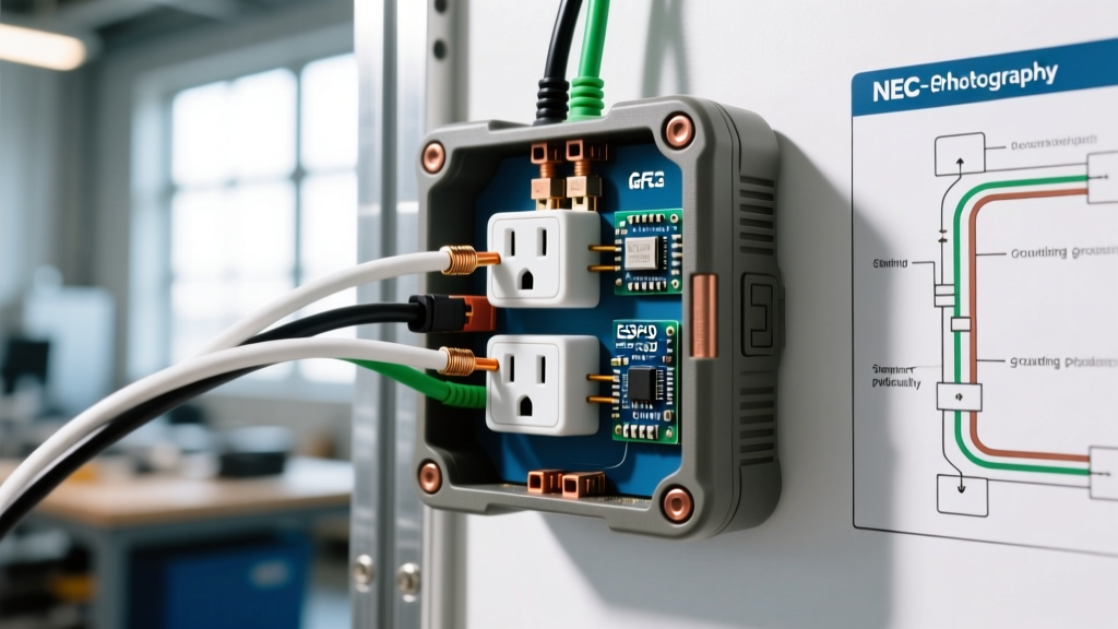
According to the OSHA electrical safety standards and NEC Article 314.16, you cannot simply stuff wires into an existing receptacle box. Adding a switch leg increases the conductor count, which generates heat. You must calculate the box fill.
For 14 AWG wire, each conductor counts as 2.0 cubic inches. Let's calculate the fill for the existing receptacle box when adding the 14/3 switch leg:
- Existing Wires: 1 hot in, 1 neutral in, 1 hot out, 1 neutral out (4 conductors = 8.0 cu in)
- New 14/3 Cable: Black, White, Red (3 conductors = 6.0 cu in)
- Equipment Grounds: All grounds count as 1 volume (2.0 cu in)
- Receptacle Device: Counts as 2 volumes (4.0 cu in)
- Internal Clamps: Counts as 1 volume (2.0 cu in)
Total Required Volume: 22.0 cubic inches. If your existing receptacle is housed in a standard 18 cu in or 20 cu in box, you must upgrade to a deeper 22.5 cu in box (such as the Carlon B625R) before proceeding. Overcrowded boxes cause insulation degradation and are a leading cause of residential electrical fires, as noted by the U.S. Consumer Product Safety Commission (CPSC).
Step-by-Step Material Prep & Safety Workflow
- Isolate and Verify (5 Minutes): Turn off the branch circuit breaker. Use the Fluke 1AC-II to check the receptacle slots, then remove the cover plate and use the Klein MM400 multimeter to verify 0V between the hot brass terminal and the ground box.
- Prepare the 14/3 NM-B (10 Minutes): Strip exactly 3/4 inch of insulation from the individual 14 AWG conductors using the Klein 11055. Strip 1 inch of the outer yellow jacket, ensuring no nick marks on the inner paper or copper.
- Terminate Grounds First (5 Minutes): Pigtail all bare copper grounds together using a Wago 221-413 lever nut, with a single pigtail routing to the receptacle's green ground screw. This ensures continuous grounding even if the device is removed.
- Make the Splices (15 Minutes): Use Wago 221 lever nuts for all splices. Unlike traditional twist-on wire nuts, Wago lever nuts eliminate the risk of under-torquing and provide a visual confirmation window to ensure the wire is fully seated against the steel bus bar.
- Torque Verification: While most residential receptacles do not mandate a torque screwdriver, tightening terminal screws to the manufacturer's spec (usually 14-16 in-lbs) prevents thermal cycling and loose connections over time.
Summary
Wiring an electrical outlet to a light switch is a straightforward process when you respect modern electrical codes. By upgrading your material list to include 14/3 NM-B cable, Wago lever connectors, and verifying your box fill calculations, you ensure your 2026 installation is safe, legal, and ready for the next generation of smart lighting controls.