
The Complete Guide to Testing Electrical Outlet Power
A dead or underperforming receptacle is one of the most common residential electrical issues. However, blindly swapping out a 15-amp duplex receptacle without diagnosing the root cause can lead to recurring failures, arcing, or severe shock hazards. To accurately test electrical outlet power, you must move beyond simple plug-in testers and understand the nuanced voltage readings that indicate healthy circuits versus hidden wiring faults.
This inspection and testing guide provides a systematic, three-phase approach to diagnosing outlet power issues, utilizing industry-standard tools and adhering to current National Electrical Code (NEC) safety protocols.
Safety Warning: Never open an electrical outlet box or test bare wires without appropriate Personal Protective Equipment (PPE), including safety glasses and voltage-rated gloves. Ensure your testing equipment is rated for CAT III or CAT IV environments to protect against transient voltage spikes.
Essential Diagnostic Tools for Outlet Testing
Professional electricians rely on a tiered toolkit to isolate faults. For a comprehensive inspection, you will need the following specific instruments:
- Non-Contact Voltage Tester (NCVT): The Klein Tools NCVT-1 (approx. $20) is ideal for initial sweeps to detect the presence of AC voltage without making direct metal-to-metal contact.
- Receptacle Tester: The Klein Tools RT105 (approx. $15) provides instant visual feedback on common wiring misconfigurations via a three-light LED matrix.
- True RMS Digital Multimeter: For precise voltage and continuity measurements, the Fluke 117 True RMS Multimeter (approx. $190) is the industry benchmark. Its non-contact voltage (NCV) feature and low-impedance (LoZ) mode are critical for eliminating phantom voltage readings.
Phase 1: Non-Contact Voltage Sweeping
Before plugging in any diagnostic tools, perform a perimeter sweep of the outlet. Insert the tip of your NCVT into the shorter (hot) slot of the receptacle. If the tool beeps and illuminates red, power is present at the face of the outlet.
Understanding Phantom Voltage
If your NCVT indicates voltage, but a plugged-in lamp does not turn on, you may be reading phantom voltage. This occurs when de-energized wires run parallel to live wires in the same conduit or Romex bundle, inducing a harmless electromagnetic charge. To confirm if the power is real, switch your multimeter to the LoZ (Low Impedance) setting, which bleeds off phantom charges and provides a true zero reading on dead circuits.
Phase 2: Receptacle Tester Diagnostics
Plug your RT105 or equivalent receptacle tester into the outlet. The combination of illuminated lights will immediately flag gross wiring errors. According to Fluke's official testing guidelines, interpreting these light patterns is the fastest way to identify miswired terminals.
Receptacle Tester Light Pattern Matrix
| Left Light (Yellow) | Center Light (Yellow) | Right Light (Red) | Diagnosis & Action Required |
|---|---|---|---|
| Off | On | On | Correct Wiring: Circuit is healthy (proceed to Phase 3 for voltage drop checks). |
| On | Off | On | Open Ground: The bare copper/green wire is disconnected. High shock risk. |
| Off | Off | On | Open Neutral: The white wire is loose or broken. Outlet will not power devices. |
| Off | On | Off | Open Hot: The black wire is disconnected or a breaker is tripped. |
| On | On | Off | Hot/Neutral Reversed: Polarity is swapped. Severe shock hazard at the lamp shell. |
| On | Off | Off | Hot/Ground Reversed: Extremely dangerous. Immediate shutdown required. |
Phase 3: Multimeter Deep-Dive and Voltage Analysis
While a receptacle tester confirms physical wire placement, it cannot tell you if the circuit is suffering from voltage drop, high resistance, or a degraded connection. For this, you must use your True RMS multimeter.
Step-by-Step Multimeter Testing Procedure
- Set the Dial: Turn your multimeter to AC Voltage (V~), ensuring the range is set to at least 200V or Auto-ranging.
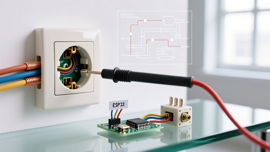
- Test Hot to Neutral: Insert the red probe into the shorter (hot) slot and the black probe into the longer (neutral) slot. A standard US residential circuit should read between 114V and 126V. If you read 104V or lower, you have a significant voltage drop issue.
- Test Hot to Ground: Move the black probe to the U-shaped ground hole. The reading should be virtually identical to your Hot-to-Neutral reading (within 1-2 volts).
- Test Neutral to Ground: Insert the red probe into the neutral slot and the black probe into the ground hole. This reading must be under 2 volts (ideally less than 0.5V). A reading higher than 2V indicates an overloaded neutral, a loose neutral connection at the panel, or a shared-neutral (MWBC) imbalance.
Common Failure Modes and Edge Cases
When electrical outlet power is intermittent or completely absent despite a healthy breaker, the fault usually lies in one of three hidden areas.
1. Backstabbed Push-In Connectors
Many builders and DIYers use the push-in holes on the back of 15-amp receptacles rather than wrapping the wire around the terminal screws. These internal spring-loaded clamps are notorious for losing their grip over time due to thermal expansion and contraction. If an outlet is dead, pull it from the box and inspect the back. If 14 AWG wires are backstabbed, remove them, strip them back to fresh copper, and secure them under the side terminal screws or use a pigtail wire nut connection.
2. Upstream GFCI and AFCI Tripping
Modern homes are wired in daisy-chain configurations. A standard bedroom or bathroom outlet might be protected by a GFCI (Ground Fault Circuit Interrupter) or AFCI (Arc Fault Circuit Interrupter) receptacle located in a completely different room, such as the garage or an adjacent bathroom. If your multimeter reads 0V across Hot-to-Neutral, trace the circuit layout. The National Fire Protection Association (NFPA) mandates strict AFCI/GFCI protection zones in the NEC; resetting an upstream tripped device often restores power to multiple downstream outlets instantly.
3. Multi-Wire Branch Circuits (MWBC)
If you open an outlet box and find two hot wires (one black, one red) connected to a single neutral (white) wire, you are dealing with an MWBC. These circuits share a neutral between two 120V legs. If the two hot wires are accidentally placed on the same phase in the breaker panel (instead of opposite phases), the shared neutral will carry the combined amperage of both circuits, leading to overheating and melted wire insulation. If you suspect an MWBC, verify that the two hot wires read exactly 240V across each other. If they read 0V across each other, they are on the same phase and must be corrected by a licensed electrician immediately.
Understanding Voltage Drop and Wire Gauge
If your Hot-to-Neutral reading drops significantly (e.g., to 108V) only when a high-draw appliance like a space heater or vacuum is plugged in, you are experiencing voltage drop under load. This is often caused by:
- Undersized Wiring: Using 14 AWG wire on a 20-amp circuit or running 12 AWG wire over excessively long distances (over 100 feet from the panel).
- Corroded Connections: Aluminum wiring (common in homes built between 1965 and 1973) that has not been treated with anti-oxidant paste and properly pigtailed to copper via COPALUM or AlumiConn connectors will develop high-resistance, heat-generating oxide layers at the terminal screws.
Final Inspection and Restoration
Once you have identified and corrected the fault—whether by tightening a loose neutral, replacing a backstabbed receptacle, or resetting an upstream GFCI—perform one final verification. Plug a known resistive load (like a 1500W hair dryer or space heater) into the outlet and re-measure the Hot-to-Neutral voltage with your multimeter. If the voltage remains stable above 114V under load, your electrical outlet power is fully restored and operating safely within NEC tolerances.