
Mastering the Basics: How to Put in an Electrical Outlet
Whether you are finishing a basement, upgrading a vintage home, or replacing a damaged receptacle, learning how to put in an electrical outlet is a foundational DIY skill. However, modern electrical codes have evolved significantly. As of the NEC 2023 and 2026 adoption cycles, simple wire twisting is no longer sufficient; precise torque specifications and tamper-resistant mandates are now standard. This guide walks you through the exact procedures, tools, and common wiring scenarios for installing standard 15-amp and 20-amp duplex receptacles.
Essential Tools and Materials
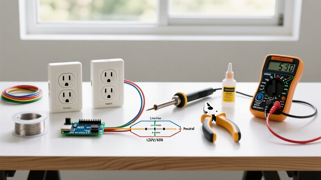
Skip the generic screwdriver set. Professional-grade electrical work requires specific tools to ensure safety and code compliance.
| Tool / Material | Purpose | Recommended Model / Spec | Approx. Cost (2026) |
|---|---|---|---|
| Non-Contact Voltage Tester | Verify dead circuit | Fluke T+PRO or Klein NCVT-2 | $35 - $50 |
| Wire Strippers | Clean insulation removal | Klein Tools 11055 (10-18 AWG) | $28 |
| Torque Screwdriver | NEC 110.14(D) compliance | IDEAL 30-150 in-lb Torque Driver | $110 - $140 |
| Receptacle | Termination point | Leviton T5262 (15A TR) or T5362 (20A TR) | $4 - $8 |
| NM-B Cable | Branch circuit wiring | Southwire 14/2 (15A) or 12/2 (20A) | $0.45 / ft |
15A vs. 20A Receptacle Scenarios
Before learning how to put in an electrical outlet, you must identify your circuit's amperacity. Mixing these up is a primary cause of residential electrical fires.
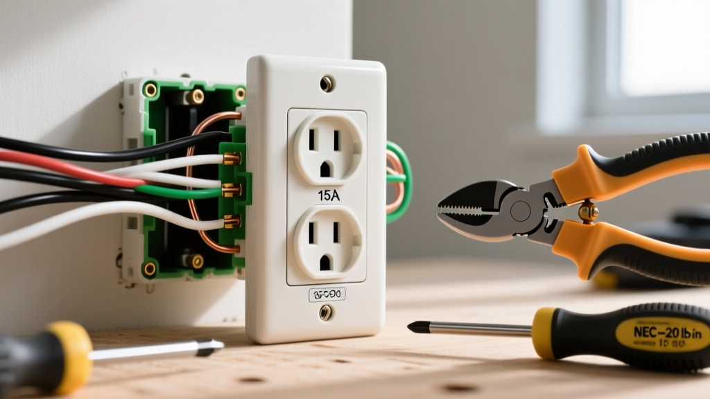
- 15-Amp Circuit: Uses 14 AWG copper wire and a 15A breaker. You can install standard NEMA 5-15R receptacles.
- 20-Amp Circuit: Uses 12 AWG copper wire and a 20A breaker. You may install NEMA 5-20R receptacles (with the T-slot) OR standard 15A receptacles, provided there is more than one outlet on the circuit (NEC 210.21(B)(3)).
Expert Insight: Never install a 20A receptacle on a 15A circuit. The physical T-slot allows appliances that draw up to 20 amps to be plugged in, which will overload 14 AWG wire before the 15A breaker trips, creating a severe fire hazard inside the walls.
Step-by-Step: How to Put in an Electrical Outlet
Step 1: Isolate and Verify Power
Turn off the breaker at the main panel. Do not rely solely on a non-contact voltage tester; plug in a lamp or use a multimeter to confirm the outlet is completely dead. The OSHA electrical safety guidelines strictly emphasize Lockout/Tagout (LOTO) procedures, even in residential settings, to prevent accidental re-energization.
Step 2: Prepare the Wires
Strip the outer NM-B jacket, leaving at least 6 to 8 inches of individual conductors inside the electrical box. Use the strip gauge molded into the back of your Leviton or Pass & Seymour receptacle. For most modern side-wiring terminals, stripping exactly 5/8 inch of insulation from the black (hot) and white (neutral) wires is ideal. This ensures no bare copper is exposed outside the terminal, and no insulation is trapped under the brass or silver screw.
Step 3: Form the J-Hook and Terminate
Using the needle-nose pliers on your wire strippers, bend the stripped ends into a tight 'J' hook. Loop the wire clockwise around the terminal screw. This is critical: as you tighten the screw (which turns clockwise), the loop will pull tighter around the shaft. If looped counter-clockwise, the wire will push out from under the screw head.
- Black (Hot) Wire: Connects to the Brass screw.
- White (Neutral) Wire: Connects to the Silver screw.
- Bare/Green (Ground): Connects to the Green screw at the bottom.
Step 4: Apply Precise Torque
This is where most DIYers fail. According to the National Electrical Code (NEC) Section 110.14(D), terminations must be tightened to the manufacturer's specified torque. For standard 15A and 20A receptacles, this is typically 12 to 14 inch-pounds. Use a calibrated torque screwdriver to click at the exact spec. Under-torquing causes high-resistance connections and arcing; over-torquing strips the brass threads or snaps the screw.
Common Wiring Scenarios
Scenario A: Replacing an Existing Receptacle
If you are swapping out an old, worn-out outlet, you will likely find multiple wires in the box (a line coming in, and a load going to the next outlet). Do not use the push-in backstab connectors. The Consumer Product Safety Commission (CPSC) notes that high-resistance connections are a leading cause of hidden electrical fires. Backstabs rely on a tiny spring clip that loses tension over time. Instead, use a red or gray Wago 221 lever nut to pigtail the incoming and outgoing wires together, adding a short 6-inch jumper wire that connects to the single side terminal of the new receptacle.
Scenario B: Split-Wiring for Switched Outlets
In living rooms, it is common to have the top half of an outlet controlled by a wall switch, while the bottom half remains always hot. To achieve this when figuring out how to put in an electrical outlet for this specific use case, you must use needle-nose pliers to snap off the small brass connecting fin on the hot side of the receptacle. Warning: Only break the brass (hot) fin. Never break the silver (neutral) fin unless you are feeding the circuit from two separate breakers with a handle tie (a multi-wire branch circuit), which requires advanced knowledge.
Crucial NEC Code Mandates for 2026
When installing new receptacles, you must adhere to the latest code cycles adopted by your local jurisdiction:
- Tamper-Resistant (TR): All 15A and 20A, 125V and 250V non-locking receptacles in dwelling units must be TR type (NEC 406.12). These feature internal shutters that prevent children from inserting single objects into the slots.
- GFCI Protection: Required in kitchens, bathrooms, garages, outdoors, crawlspaces, and within 6 feet of sinks or wet areas.
- AFCI Protection: Arc-Fault Circuit Interrupters are now required on almost all 120V, single-phase, 15A and 20A branch circuits supplying outlets in living spaces, bedrooms, and hallways.
Troubleshooting and Failure Modes
Even when you know how to put in an electrical outlet correctly, testing is mandatory. Use a 3-light receptacle tester (like the Sperry ET6402). Common failure modes include:
- Open Ground: The bare copper wire isn't making solid contact with the box or the green screw. Check your ground pigtails.
- Reversed Polarity: The hot and neutral wires are swapped. This is incredibly dangerous because the appliance's internal switch will only disconnect the neutral, leaving the device energized even when turned off.
- Bootleg Ground: A previous owner jumpered the neutral terminal to the ground screw to fool a tester. This creates a severe shock hazard if the neutral wire ever breaks upstream.
Frequently Asked Questions
Can I daisy-chain outlets using the push-in holes on the back?
While the NEC technically allows listed push-in connectors for 14 AWG solid wire, professional electricians universally avoid them due to long-term failure rates. Always use side-wiring with terminal screws or Wago lever-nut pigtails for reliable, high-surface-area connections.
What if the electrical box is too shallow for the new outlet?
NEC Article 314 dictates box fill calculations. A standard single-gang plastic box is 18 to 22 cubic inches. If you are adding pigtails, grounding clips, and cable clamps, you may exceed the box fill limit. Upgrade to a 22.5 cubic-inch deep box to prevent wire crushing and insulation damage when pushing the receptacle back in.