
The Intersection of Safety and Code: Wiring Outlets the Right Way
Learning how to wire an electrical outlet goes far beyond simply connecting black to brass and white to silver. While the basic physics of a 120-volt duplex receptacle are simple, the National Electrical Code (NEC) mandates strict installation parameters to prevent arc faults, thermal overloads, and child electrocution. As a DIYer or apprentice electrician, ignoring these code requirements can lead to failed inspections, voided home insurance, or catastrophic electrical fires.
This guide breaks down the exact NEC code requirements for outlet wiring, complete with box fill mathematics, torque specifications, and step-by-step installation protocols for standard 15-amp and 20-amp circuits.
Core NEC Code Requirements for Receptacle Wiring
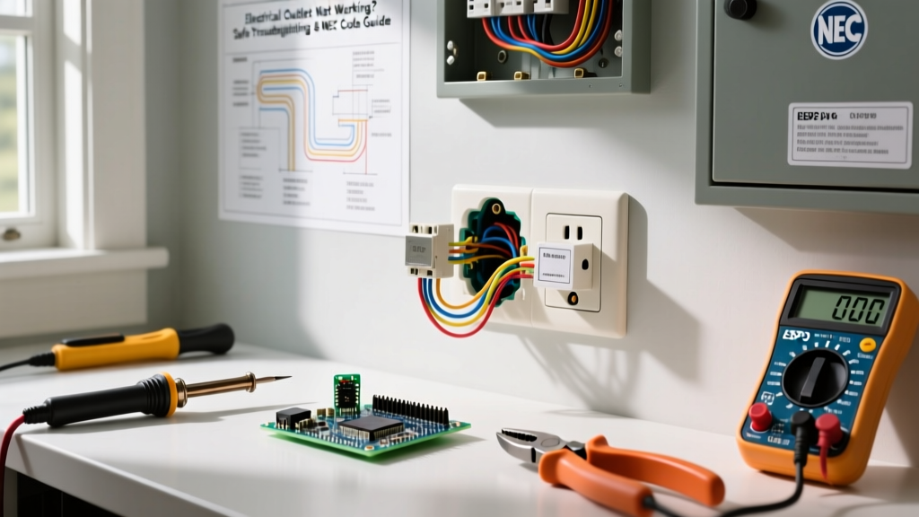
Before stripping a single wire, you must understand the governing codes that dictate outlet installation. The National Fire Protection Association (NFPA) updates the NEC every three years, and modern installations must adhere to these critical articles.
1. Tamper-Resistant (TR) Mandate (NEC 406.12)
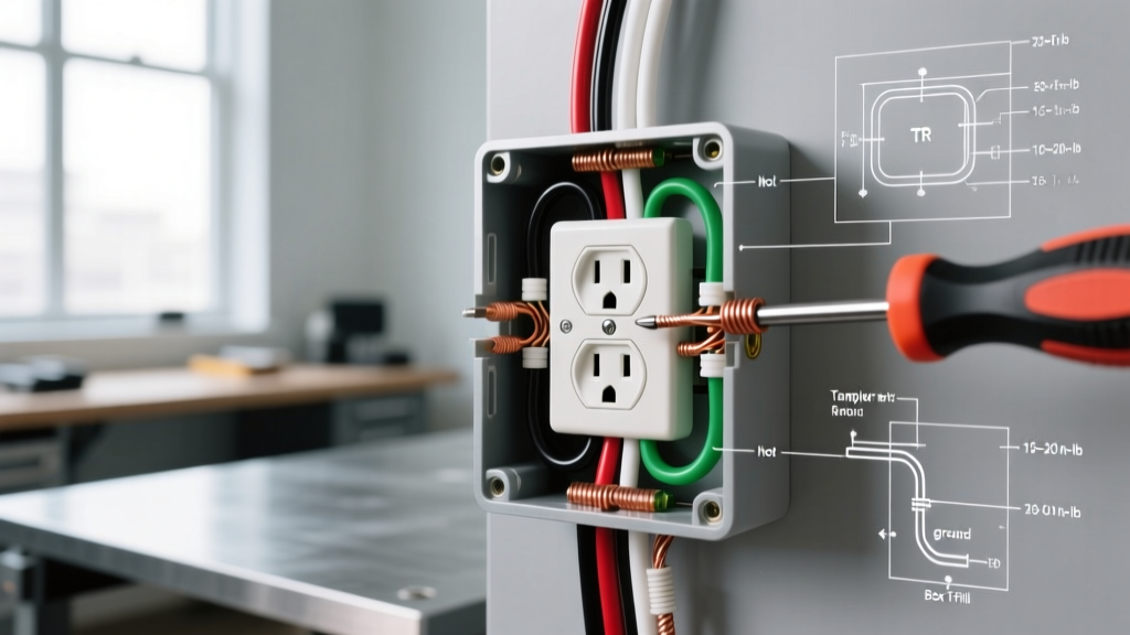
Gone are the days of installing standard, non-TR receptacles in living spaces. NEC 406.12 requires all 15-amp and 20-amp, 125-volt and 250-volt receptacles installed in dwelling units to be Tamper-Resistant. These feature internal spring-loaded shutters that only open when equal pressure is applied to both slots simultaneously. A standard Leviton T5320-W 15A TR receptacle costs roughly $2.50 to $3.50, making the safety upgrade economically negligible compared to older $0.80 builder-grade models.
2. Box Fill Calculations (NEC 314.16)
Overcrowding a junction or device box causes wire insulation damage and traps heat. You must calculate box fill based on the largest conductor entering the box. For standard 12 AWG copper wire, each conductor counts as 2.25 cubic inches.
Pro Tip: A standard single-gang 'nail-on' plastic box typically offers 18 to 22.5 cubic inches of volume. Always check the stamp inside the box before drywalling.
End-of-Run 12 AWG Box Fill Math:
- 1 Hot (Black): 2.25 cu in
- 1 Neutral (White): 2.25 cu in
- 1 Ground (Bare/Green): 2.25 cu in (All grounds count as a single conductor allowance)
- Device (Receptacle): 4.50 cu in (Counts as two conductors)
- Total Required: 11.25 cubic inches (Easily fits an 18 cu in box)
3. GFCI and AFCI Protection (NEC 210.8 & 210.12)
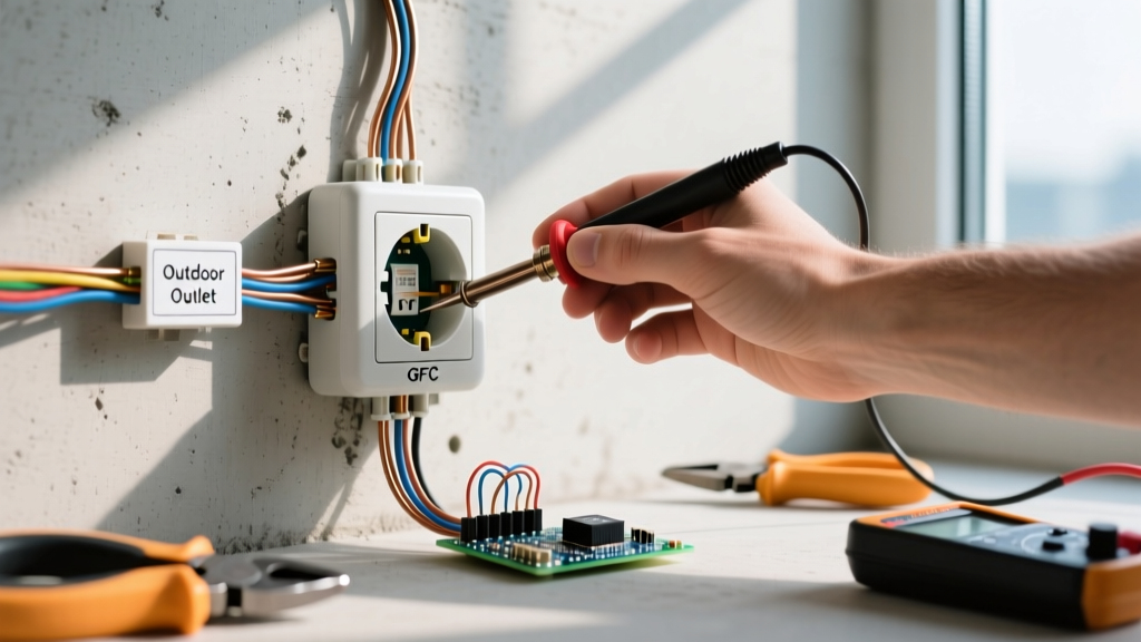
Ground Fault Circuit Interrupter (GFCI) protection is mandatory in wet or damp locations: kitchens, bathrooms, garages, crawlspaces, and outdoors (NEC 210.8). Arc Fault Circuit Interrupter (AFCI) protection is required for nearly all 120V, 15A and 20A branch circuits supplying living areas, bedrooms, and hallways (NEC 210.12). AFCI is typically handled at the breaker panel, while GFCI can be achieved via a GFCI breaker or a local GFCI receptacle (like the Hubbell GFTR20-W, retailing around $22).
Step-by-Step: How to Wire an Electrical Outlet to Code
Follow this precise sequence to ensure a safe, code-compliant termination.
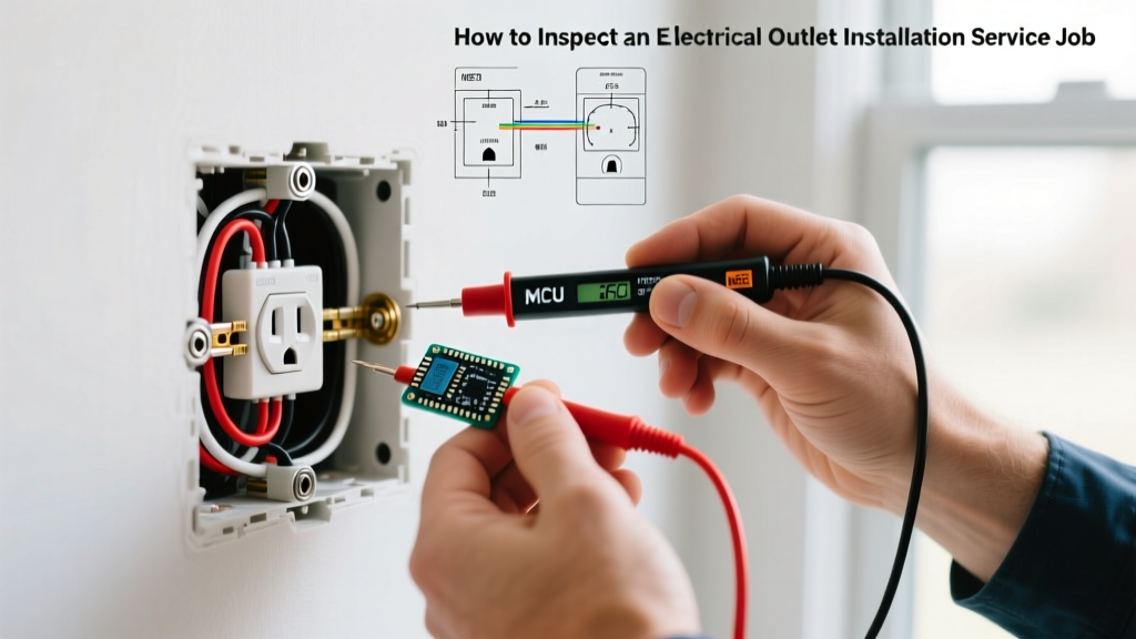
- Verify Power and Strip to Gauge: Confirm the breaker is OFF using a non-contact voltage tester (NCVT) and a multimeter. Strip the Romex sheathing leaving at least 1/4 inch inside the box. Use the built-in strip gauge on the back of the receptacle—usually 3/4 inch for side-wiring. Do not nick the copper.
- Pigtail with Lever Nuts: If passing power downstream, avoid bulky twist-on wire nuts which consume valuable box volume. Instead, use WAGO 221 3-port lever nuts. They require less stripped wire (11mm), provide a gas-tight connection, and feature a built-in test port for your multimeter probes.
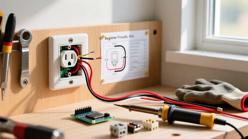
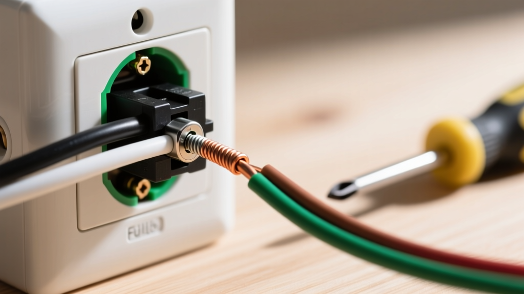
- Form the Shepherd's Hook (Side-Wiring): Using linesman pliers, bend the stripped 12 AWG or 14 AWG copper wire into a tight, clockwise loop. The clockwise direction ensures the tightening action of the screw pulls the loop closed rather than pushing it outward.
- Terminate Ground First: Connect the bare copper ground to the green grounding screw. If using a metal box, you must also bond the box using a grounding pigtail and a green grounding clip or 10-32 ground screw.
- Connect Neutral and Hot: Loop the white neutral wire onto the silver screw (left side) and the black hot wire onto the brass screw (right side). Ensure no bare copper is exposed outside the terminal, and no insulation is trapped under the screw head.
- Apply Calibrated Torque: This is the most skipped step by DIYers. NEC 110.14(D) requires terminations to be torqued to the manufacturer's specifications.
- Fold and Secure: Carefully fold the bare ground into the back corners of the box, followed by the neutrals, and finally the hots. Push the receptacle in evenly, ensuring no wires are pinched against the sharp edges of the metal or plastic box. Secure the yoke using the provided 6-32 machine screws, using a level to ensure the faceplate will sit perfectly straight.
Torque Specifications and Wire Preparation Data
Under-torqued connections cause arcing and thermal expansion/contraction, leading to fires. Over-torqued connections strip threads or shear the wire. Refer to this matrix for standard 15A/20A commercial-grade receptacles:
| Wire Gauge | Breaker Size | Strip Length | Torque Spec (in-lbs) | Tool Required |
|---|---|---|---|---|
| 14 AWG | 15 Amp | 5/8 inch | 14 in-lbs | Calibrated Torque Screwdriver |
| 12 AWG | 20 Amp | 3/4 inch | 16 in-lbs | Calibrated Torque Screwdriver |
| 10 AWG | 30 Amp (Rare for standard duplex) | 7/8 inch | 25 in-lbs | Calibrated Torque Wrench/Driver |
Backstabbing vs. Screw-Terminal Back-Wiring
When researching how to wire an electrical outlet, you will encounter the push-in 'backstab' holes on the rear of builder-grade receptacles. Never use spring-loaded push-in backstab connections. They rely on a tiny metal tang that bites into the wire, offering minimal surface contact. They are notorious for failing under high-draw loads (like space heaters or vacuums), causing melting and fires.
However, screw-terminal back-wiring (found on commercial/spec-grade receptacles) is entirely code-compliant and preferred by many master electricians. In this method, you insert a straight-stripped wire into the rear clamp and tighten the side screw, which mechanically drives a heavy-duty brass plate down onto the wire. This allows for faster installation and two wires per terminal (e.g., line and load on the same screw) without pigtailing.
Common Code Violations to Avoid
- Reversed Polarity: Swapping hot and neutral. This leaves the device's internal switch on the neutral leg, meaning the appliance remains energized at 120V even when turned 'off'.
- Bootleg Grounds: Jumpering the neutral terminal to the ground screw to trick a 3-prong tester. This is highly illegal and lethal; if the neutral breaks upstream, the appliance chassis becomes energized at 120V.
- Over-stripping: Leaving 1/4 inch of bare copper exposed outside the terminal. This creates a shock hazard and a potential short circuit if wires shift inside the box.
- Failing to Break the Hot Fin on Split Receptacles: In living rooms with switched half-hot outlets (often fed by a Multi-Wire Branch Circuit or a switch loop), the brass connecting fin between the top and bottom hot screws MUST be snapped off. Failing to do so will bypass the wall switch or cause a direct phase-to-phase short circuit if fed by a MWBC.
- Missing Faceplate Bonding: If using a metal faceplate on a metal box, the receptacle yoke must be firmly seated against the box to ensure the grounding path is continuous.
Frequently Asked Questions
Can I use 14 AWG wire on a 20-amp breaker?
No. NEC 240.4(D) strictly limits 14 AWG copper to 15-amp overcurrent protection. If your breaker is 20A, you must use a minimum of 12 AWG wire and a 20-amp rated receptacle (identified by the T-slot neutral blade).
Do I need to pigtail the ground wire?
Yes, if you are passing the ground through to a downstream outlet. You must connect all incoming and outgoing grounds together with a wire nut or Wago connector, and add a short 'pigtail' to connect to the receptacle's green screw. The ground path must never rely on the receptacle's internal yoke.
What is the difference between a 15A and 20A receptacle?
A 15A receptacle has two parallel vertical slots. A 20A receptacle has one vertical slot and one T-shaped horizontal slot. Per NEC 210.21(B)(1), a single receptacle on a 20A circuit must be rated for 20A. However, if there are multiple receptacles on a 20A circuit, 15A receptacles are permitted.
For deeper technical analysis on grounding and bonding, refer to the extensive code breakdowns provided by Mike Holt Enterprises, a premier authority on NEC applications. Always consult your local Authority Having Jurisdiction (AHJ), as local amendments can supersede national baseline codes.