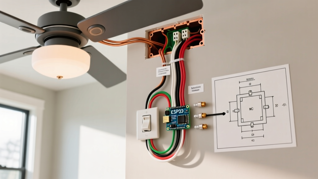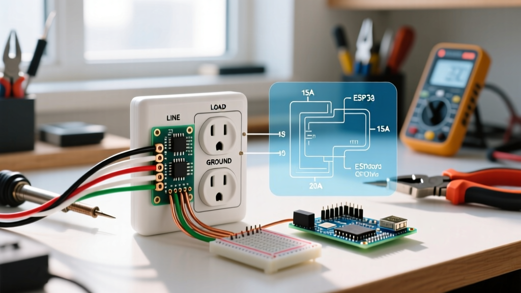

Introduction to Residential Receptacle Wiring
For DIYers and apprentice electricians, interpreting a wiring diagram electrical outlet schematic can feel like reading a foreign language. However, standard 120-volt residential receptacles follow a highly predictable, standardized logic governed by the National Electrical Code (NEC). Whether you are replacing a damaged duplex receptacle or running a new branch circuit, understanding the fundamental wiring topology is critical for safety and code compliance.
In this 2026 beginner installation tutorial, we will decode the standard wiring diagram for electrical outlets, break down the anatomy of a modern receptacle, and provide a step-by-step installation flow utilizing professional-grade tools and torque specifications.
CRITICAL SAFETY WARNING: Always turn off the power at the main service panel or local subpanel before beginning any electrical work. Verify the absence of voltage using a non-contact voltage tester and a multimeter. According to the Electrical Safety Foundation International (ESFI), electrical fires cause hundreds of fatalities annually; never bypass Lockout/Tagout (LOTO) procedures.
Anatomy of a Standard Duplex Receptacle
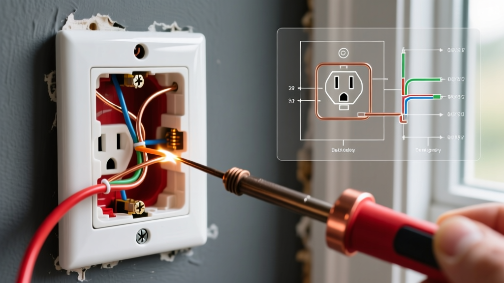
Before applying any wiring diagram, you must understand the physical termination points on a standard NEMA 5-15R or 5-20R receptacle. Modern devices from manufacturers like Leviton and Hubbell feature three distinct terminal zones:
- Brass Screws (Hot/Line): These connect to the ungrounded conductor (typically black or red insulation). This carries the 120V alternating current from the breaker panel.
- Silver Screws (Neutral): These connect to the grounded conductor (white or gray insulation). This completes the circuit back to the panel bus bar.
- Green Screw (Ground): This connects to the equipment grounding conductor (bare copper or green insulation). It provides a low-impedance fault path to trip the breaker during a short circuit.
Line vs. Load: A Common Point of Confusion
When reviewing a wiring diagram electrical outlet guide, beginners often confuse 'Line' and 'Load' terminals. On a standard (non-GFCI/AFCI) duplex receptacle, the two brass screws and two silver screws are internally bonded via metal break-off tabs. Therefore, there is no functional difference between the top and bottom screws; you simply use one set for the incoming power (Line) and the other set to pass power downstream (Load) to the next outlet in a daisy-chain. If you are installing a GFCI receptacle, however, distinguishing Line (incoming) from Load (downstream protection) is strictly enforced by the manufacturer's diagram.
15A vs. 20A Receptacle Comparison Matrix
Selecting the correct receptacle rating for your branch circuit is a foundational NEC requirement. Below is a comparison matrix to help you match your wiring diagram to the correct hardware.
| Feature | 15-Amp Circuit (Standard) | 20-Amp Circuit (Heavy Duty) |
|---|---|---|
| Breaker Size | 15A Single Pole | 20A Single Pole |
| Wire Gauge (Copper) | 14 AWG (Romex 14/2) | 12 AWG (Romex 12/2) |
| Receptacle NEMA Config | NEMA 5-15R (Two parallel slots) | NEMA 5-20R (One T-slot, one straight) |
| 2026 Avg. Hardware Cost | $1.25 - $2.00 (e.g., Leviton 5320-W) | $2.50 - $4.00 (e.g., Leviton 5362-W) |
| NEC Pigtailing Rule | Allowed to feed through device | Neutral must be pigtailed if feeding downstream (NEC 406.4) |
Essential Tool Checklist for 2026
Professional results require professional tools. Avoid using utility knives to strip wires, which nicks the copper and creates high-resistance hot spots.
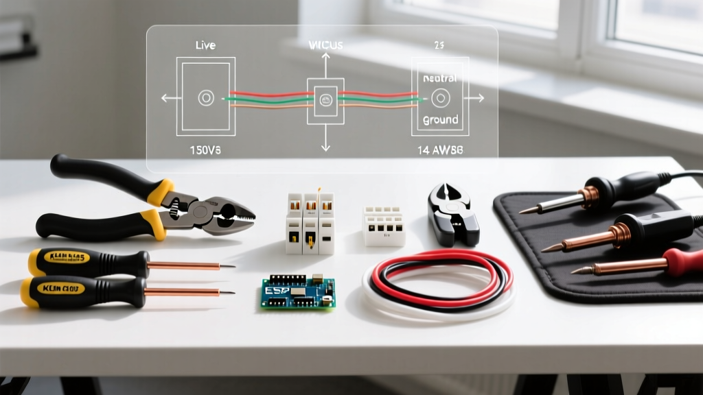
- Wire Strippers: Klein Tools 11055 (10-20 AWG). Features a built-in 3/4-inch strip gauge perfect for standard receptacle loops.
- Voltage Tester: Milwaukee 48-22-2802 Dual-Range Non-Contact Voltage Tester.
- Torque Screwdriver: Klein Tools 10250. The 2026 NEC (Section 110.14(D)) strictly mandates the use of a calibrated torque tool for terminations to prevent thermal loosening.
- Side Cutters & Needle Nose Pliers: For forming precise J-hooks and trimming excess ground wire.
Step-by-Step Installation Flow
Follow this exact sequence to execute your wiring diagram safely and cleanly.
Step 1: Verify Power and Prep the Box
Confirm the circuit is dead. Remove the old receptacle and inspect the electrical box. Ensure there is adequate cubic inch volume per NEC Article 314. For a standard single receptacle with one incoming and one outgoing cable, a 22-cubic-inch 'old work' or 'new work' box is typically sufficient.
Step 2: Strip and Dress the Conductors
Using your Klein 11055 strippers, remove exactly 3/4-inch of insulation from the black, white, and ground wires. The internal strip gauge on the tool ensures you do not strip too much (leaving exposed copper outside the terminal) or too little (trapping insulation under the screw head, causing an open circuit).
Step 3: Form the J-Hook
Use your needle-nose pliers to bend the stripped copper into a clockwise 'J-hook'. The clockwise orientation is critical: as you tighten the screw clockwise, the hook pulls tighter around the screw shaft. A counter-clockwise hook will be pushed out from under the screw head as it tightens.
Step 4: Terminate and Torque
Hook the black wire to the brass screw, the white wire to the silver screw, and the bare copper to the green ground screw. Set your torque screwdriver to the manufacturer's specification—typically 14 in-lbs for standard 15A/20A receptacles. Tighten until the tool clicks. Do not overtighten, as this can strip the brass threads or snap the screw head.
Step 5: Pigtailing the Ground
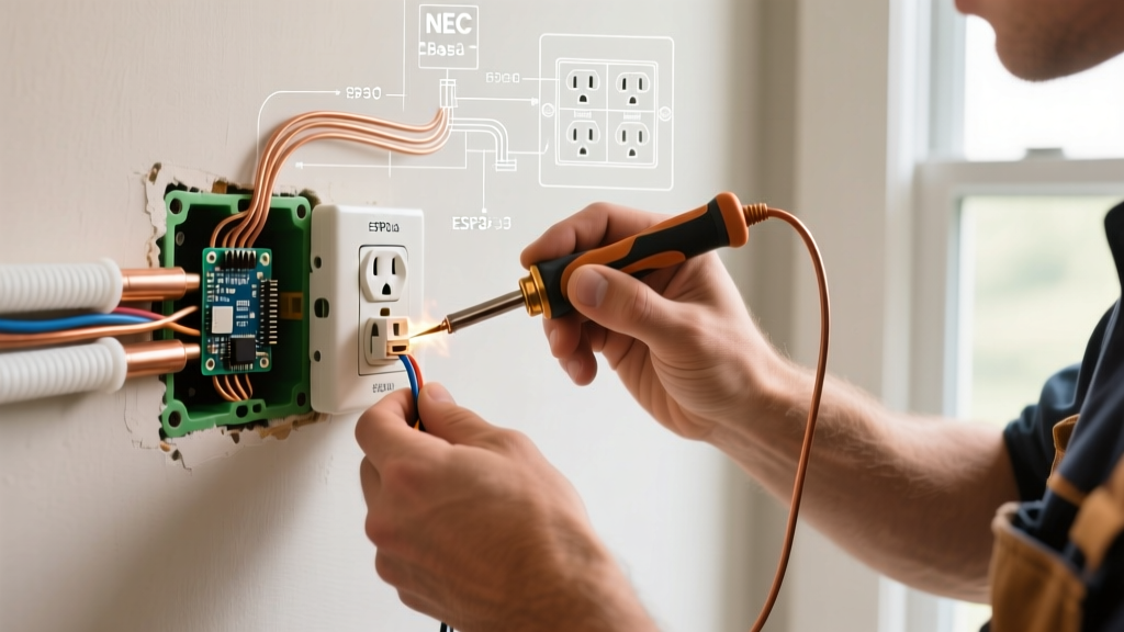
If you are feeding another outlet downstream, do not daisy-chain the ground wire through the receptacle's green screw. Instead, use a wire nut or a push-in connector (like a Wago 221) to join the incoming ground, the outgoing ground, and a 6-inch 'pigtail' that connects to the receptacle's green screw. This ensures the grounding path remains intact even if the receptacle is removed.
Common Beginner Mistakes & Troubleshooting
Even with a perfect wiring diagram electrical outlet reference, physical execution errors can lead to catastrophic failures. Avoid these common pitfalls:
- Backstabbing (Push-In Terminals): Many cheap receptacles feature spring-loaded push-in holes on the back. Never use these. Over time, thermal expansion and contraction cause the spring tension to relax, leading to high-resistance arcing and melted plastic. Always use the side-screw terminals or the 'back-wire' clamp plates found on premium spec-grade receptacles.
- Reversed Polarity: Swapping the black (hot) and white (neutral) wires. While the outlet will still power a lamp, the internal switch of the appliance will break the neutral rather than the hot wire, leaving the appliance energized and creating a severe shock hazard. Use a $15 receptacle tester to verify correct polarity before closing the drywall.
- Bootleg Grounds: In older homes lacking a ground wire, some beginners mistakenly jumper the neutral screw to the ground screw to trick a tester. This is highly illegal and deadly. If a neutral fault occurs downstream, the metal chassis of any plugged-in appliance will become fully energized at 120V. If no ground exists, you must install a GFCI receptacle and label it 'No Equipment Ground' per NEC 406.4(D)(2).
Final Inspection and Code Compliance
According to the National Fire Protection Association (NFPA), proper termination and adherence to torque specifications drastically reduce residential electrical fires. Before pushing the wires back into the box, fold them neatly in a Z-pattern. Ensure no bare ground wires are resting against the hot brass terminals. Finally, secure the receptacle to the box using the provided 6-32 machine screws, ensuring the device sits flush and plumb against the wall surface.
For further reading on residential wiring safety standards and historical data on electrical fire prevention, consult the U.S. Consumer Product Safety Commission (CPSC) Electrical Safety Guide. By respecting the diagram, utilizing calibrated tools, and following NEC mandates, you ensure a safe, reliable, and code-compliant installation.