
The Reality of Powerline Communication in 2026
While Wi-Fi 7 mesh systems and MoCA (Multimedia over Coax) adapters dominate the home networking landscape, routing internet through electrical outlet wiring—technically known as Powerline Communication (PLC)—remains a critical fallback. For homes lacking coaxial drops or Ethernet CAT6 runs, PLC adapters like the TP-Link TL-PA9020P (HomePlug AV2) or the Netgear PLP2000 (ITU-T G.hn) utilize existing copper wiring to bridge network gaps. However, marketing claims of 'AV2000' or '2400 Mbps' speeds are strictly theoretical PHY (physical layer) rates. Real-world throughput is entirely dependent on the physical and electrical integrity of your receptacles and branch circuits.
This inspection and testing guide provides a systematic approach to evaluating your electrical infrastructure for PLC viability, identifying signal-killing roadblocks, and benchmarking actual network performance using industry-standard diagnostic tools.
Pre-Inspection: Identifying Electrical Roadblocks
Before plugging in a $100 PLC kit, you must understand how high-frequency data signals (typically operating between 2 MHz and 86 MHz) interact with standard 60 Hz AC power infrastructure. According to the Federal Communications Commission (FCC), power lines are inherently unshielded and noisy environments. The following electrical components are notorious for degrading or entirely blocking PLC signals:
- Surge Protectors and Power Strips: The metal oxide varistors (MOVs) and capacitive filtering in surge protectors are designed to shunt high-frequency voltage spikes to ground. Unfortunately, they cannot distinguish between a power surge and a 50 MHz G.hn data signal, effectively shorting your internet connection to the ground plane.
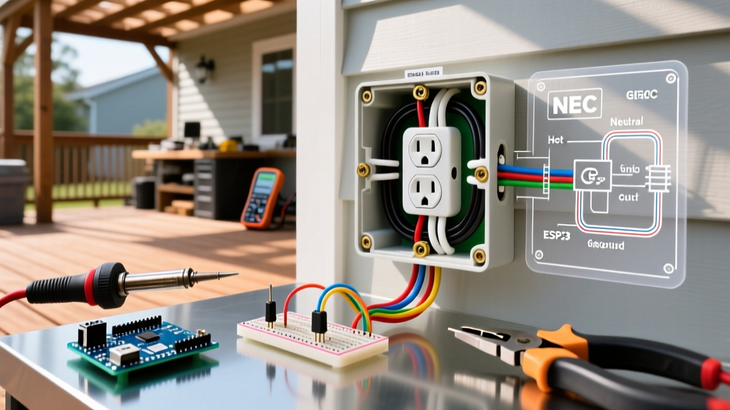
- GFCI and AFCI Receptacles/Breakers: Ground Fault and Arc Fault protection devices utilize high-frequency filtering to detect anomalous waveforms. This filtering heavily attenuates the frequencies used by Powerline adapters. TP-Link's official support documentation explicitly warns against plugging PLC adapters into GFCI-controlled outlets due to severe packet loss and synchronization failures.
- Switching Power Supplies: Cheap LED bulb drivers, unbranded phone chargers, and older dimmer switches generate massive electromagnetic interference (EMI) in the 2-30 MHz range, directly overlapping with the lower bands of HomePlug AV2.
Step-by-Step Physical Outlet Inspection Protocol
If you are experiencing sub-par speeds, the physical condition of the receptacle is the first point of failure. Follow this inspection checklist:
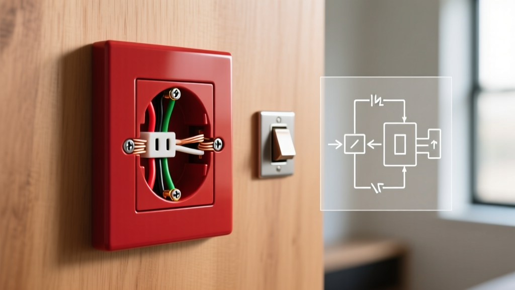
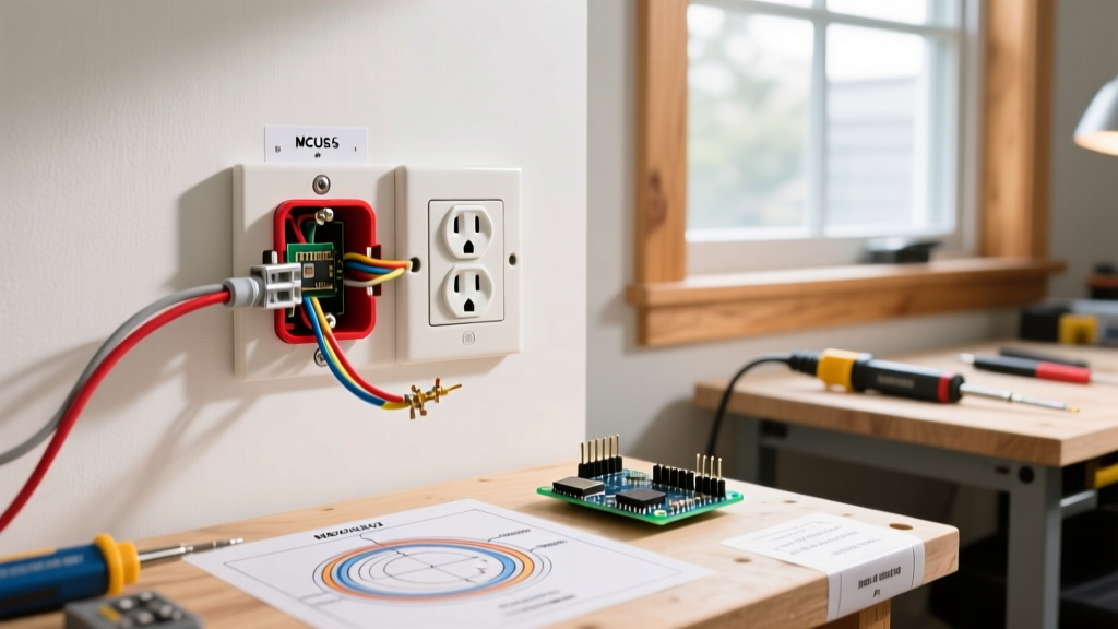
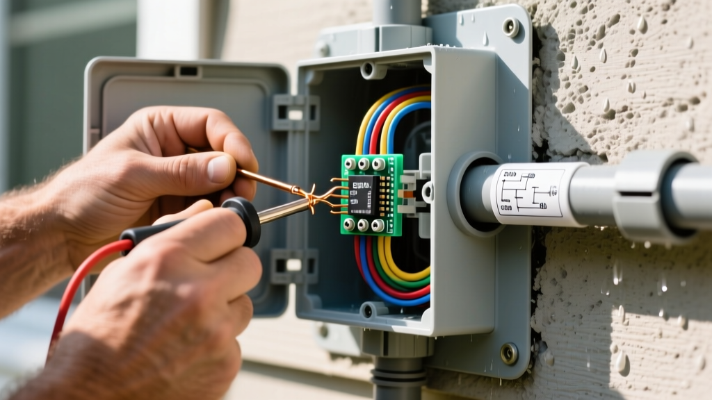
- Remove the Faceplate and Inspect Terminations: Turn off the breaker and pull the receptacle out. If the wiring is 'backstabbed' (pushed into the quick-insert holes on the back), this is a primary culprit for signal attenuation. Push-in connectors rely on weak spring tension, leading to micro-arcing and high impedance at high frequencies. Remedy: Move the wires to the screw terminals, wrapping them clockwise around the screw for a solid mechanical and electrical bond.
- Check for Aluminum Wiring: If your home was built between 1965 and 1973, you may have aluminum branch wiring. Aluminum has higher resistance than copper and oxidizes rapidly at termination points, creating a high-impedance barrier that destroys PLC signal-to-noise ratios (SNR). PLC adapters are generally not recommended on un-remediated aluminum circuits.
- Identify Circuit Topology (Daisy Chaining): Trace the circuit to see how many outlets are daisy-chained together. Every junction, wire nut, and receptacle pass-through introduces insertion loss. A PLC signal traversing 15 daisy-chained outlets will suffer significantly more attenuation than one crossing just three.
Network Stress Testing with iPerf3
Do not rely on web-based speed tests to diagnose your powerline connection. Web tests measure your ISP's throughput, not the local bottleneck of your electrical wiring. To accurately test the link between two PLC adapters, use iPerf3, a command-line network testing tool.
Setting Up the Test Environment
Connect a PC via Ethernet to the transmitting PLC adapter (near the router) and a second PC via Ethernet to the receiving adapter. Ensure both PCs are on the same local subnet.
On the receiving PC (Server), open your terminal and run:
iperf3 -sOn the transmitting PC (Client), run a multi-threaded TCP test to saturate the link:
iperf3 -c [Server_IP_Address] -P 4 -t 30 -RNote: The -R flag reverses the test, measuring download throughput, which is typically the more critical metric for end-users.
Interpreting the Data
Look beyond the final 'Bits per second' metric. Pay close attention to Retr (TCP Retransmissions). If you see hundreds of retransmissions over a 30-second window, your electrical environment is highly noisy, causing the PLC adapters to constantly drop and request missing packets. A healthy powerline link should show zero or near-zero retransmissions on a local wired test.
Real-World Performance Matrix: AV2 vs. G.hn
When selecting or upgrading equipment, understanding the underlying chipset standard is vital. Below is a realistic performance matrix based on 2026 field testing across standard residential 14 AWG and 12 AWG copper wiring.
| Standard | Frequency Band | Theoretical PHY Rate | Real-World Max (Same Phase) | Real-World Max (Cross-Phase) | Best Use Case |
|---|---|---|---|---|---|
| HomePlug AV2 (MIMO) | 2 - 68 MHz | 2000 Mbps | 350 - 450 Mbps | 80 - 150 Mbps | Standard streaming, smart home hubs |
| ITU-T G.hn (Wave 2) | 2 - 86 MHz | 2400 Mbps | 500 - 700 Mbps | 150 - 250 Mbps | Low-latency gaming, 4K/8K local NAS |
Source: Aggregated field data referencing Netgear G.hn technical specifications and independent throughput benchmarking.
Advanced Troubleshooting: Phase Coupling and Noise
The Split-Phase Problem in North America
Most North American homes utilize a 240V split-phase electrical system, meaning your breaker panel supplies two distinct 120V legs (Phase A and Phase B). If your router's PLC adapter is plugged into an outlet on Phase A, and your bedroom adapter is on Phase B, the high-frequency data signal must travel all the way out to the utility pole transformer, cross the primary winding, and come back inside to reach the other phase. This massive detour introduces catastrophic signal attenuation.
The Fix: You must install a Passive Phase Coupler (such as the SignaLinc 2406) directly into a 240V dryer or oven receptacle, or hardwire it at the breaker panel. This device safely bridges the high-frequency PLC signals between Phase A and Phase B without mixing the 60 Hz AC power, often doubling or tripling cross-phase throughput instantly.
Isolating Switching Power Supply Interference
If your iPerf3 test shows massive jitter and retransmissions, you likely have EMI pollution on the circuit. To isolate the culprit:
- Turn off all non-essential breakers in the home, leaving only the circuit powering the PLC adapters and your router.
- Run the iPerf3 test again. If speeds normalize, the noise is coming from another circuit (signals can couple between parallel wires in the walls).
- Turn breakers back on one by one. When the iPerf3 throughput suddenly drops, you have identified the noisy circuit.
- Inspect that circuit for cheap LED bulbs, older aquarium pumps, or unbranded USB wall chargers. Replacing these with UL-listed, EMI-shielded alternatives will clear the noise floor.
Final Verdict: When to Abandon PLC
Routing internet through electrical outlet infrastructure is a brilliant stopgap, but it is not a panacea. If your home features aluminum wiring, extensive multi-gang daisy chains, or if the physical distance between the adapters exceeds 300 meters of wire length, the Signal-to-Noise Ratio will drop below the 15 dB threshold required for stable MIMO modulation. In these edge cases, abandon the powerline adapters and invest in a MoCA 2.5 network over existing coaxial cables, or run a dedicated CAT6a drop to guarantee a stable, gigabit-capable backbone.