
Understanding the Modern Wiring Diagram for House Light Switch Setups
When evaluating a wiring diagram for house light switch installations, safety and code compliance must dictate every connection. The National Electrical Code (NEC) undergoes continuous revisions to address modern electrical loads and smart home technologies. As of 2026, local jurisdictions are strictly enforcing updated NEC articles regarding switch loops, box fill capacities, and termination torque. Relying on outdated diagrams found on legacy forums can result in severe fire hazards, failed inspections, and lethal shock risks.
This guide dissects the anatomy of a code-compliant single-pole switch installation, referencing specific NEC articles, exact cubic-inch calculations, and manufacturer torque specifications to ensure your project meets the highest safety standards.
The Death of the Old Switch Loop: NEC 404.2(C)
Historically, electricians used a 'switch loop' wiring diagram for house light switch runs that only sent a hot and a switched-hot wire to the switch box, omitting the neutral. This was done to save copper. However, the proliferation of smart switches, timers, and occupancy sensors—which require a continuous 120V neutral to power their internal Wi-Fi or Zigbee radios—changed the landscape.
NEC 404.2(C) Switches Controlling Lighting Loads: Where switches control lighting loads supplied by grounded general purpose branch circuits, the grounded circuit conductor (neutral) shall be provided at the switch location.
If your wiring diagram does not include a 3-wire cable (e.g., 14/3 or 12/3 NM-B) running from the ceiling fixture to the switch box to accommodate the neutral, it is a direct code violation. Using a 14/2 cable and attempting to bootleg a neutral from the ground wire is a deadly practice that will immediately trip modern GFCI/AFCI breakers and pose a severe electrocution hazard.
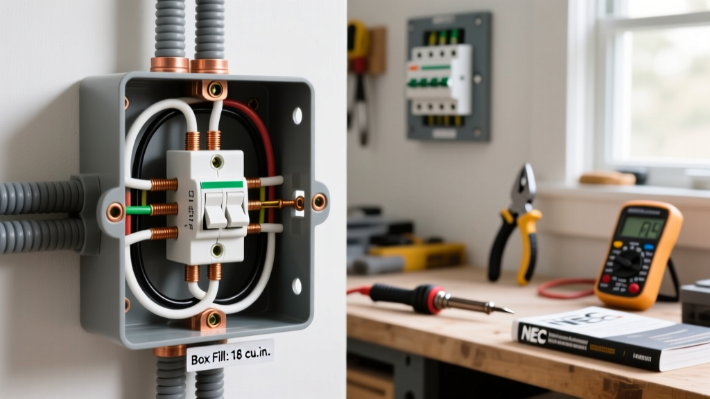
Box Fill Calculations: Preventing Overcrowding (NEC Article 314)
A critical failure point in DIY electrical work is ignoring box fill calculations. Cramming too many wires into a standard electrical box damages wire insulation and creates heat buildup. According to NFPA 70 National Electrical Code Article 314.16, you must calculate the required cubic inch capacity based on the conductors, clamps, and devices present.
NEC 314.16(B) Allowable Fill Table
| Wire Gauge | Cubic Inches per Wire | Device (Switch) Allowance | Ground Wire Allowance |
|---|---|---|---|
| 14 AWG | 2.0 cu in | 4.0 cu in (2x wire vol) | 2.0 cu in (1x wire vol) |
| 12 AWG | 2.25 cu in | 4.5 cu in (2x wire vol) | 2.25 cu in (1x wire vol) |
| 10 AWG | 2.5 cu in | 5.0 cu in (2x wire vol) | 2.5 cu in (1x wire vol) |
Real-World Calculation Example
Imagine you are wiring a standard single-pole switch using 14 AWG wire. You have one 14/2 cable entering (power in) and one 14/3 cable leaving (to the fixture with neutral).
- Hot wires: 2 wires x 2.0 = 4.0 cu in
- Neutral wires: 2 wires x 2.0 = 4.0 cu in
- Switched-Hot: 1 wire x 2.0 = 2.0 cu in
- Equipment Grounds: 1 allowance x 2.0 = 2.0 cu in
- Switch Device: 1 allowance x 4.0 = 4.0 cu in
- Total Required: 16.0 cubic inches.
A standard single-gang nail-on box like the Carlon B618R (retailing around $2.15) provides exactly 18 cubic inches, making it compliant. Using a shallow 12.5 cubic inch handy box for this configuration is a severe violation.
Step-by-Step Code-Compliant Single-Pole Installation
For a standard 15-Amp lighting circuit, utilize a reliable commercial-grade switch such as the Leviton Decora 5601 (approx. $3.50). Commercial-grade switches feature thicker brass terminal screws and deeper wire gauges that resist arcing over decades of use.
- Verify Power & Lockout: Turn off the 15A breaker and verify zero voltage using a CAT III or CAT IV non-contact voltage tester and a multimeter. OSHA electrical safety guidelines mandate strict lockout/tagout procedures even in residential settings to prevent accidental re-energization.
- Strip Insulation Precisely: Use a precision wire stripper (e.g., Klein Tools 11055) to strip exactly 3/4 inch of insulation. Exposing too much bare copper outside the terminal creates a shock hazard; stripping too little causes the screw to bite into the insulation, leading to high-resistance arcing.
- Form the J-Hook: Bend the wire into a tight 'J' hook. Loop it clockwise around the brass terminal screw. This ensures that tightening the screw pulls the loop tighter rather than pushing it out.
- Pigtail the Grounds: Never daisy-chain grounds through the switch yoke. Use a green wire nut to pigtail the bare copper ground wires together with a 6-inch jumper leading to the switch's green ground screw and the metal box (if applicable).
Torque Specifications: The Hidden Code Requirement
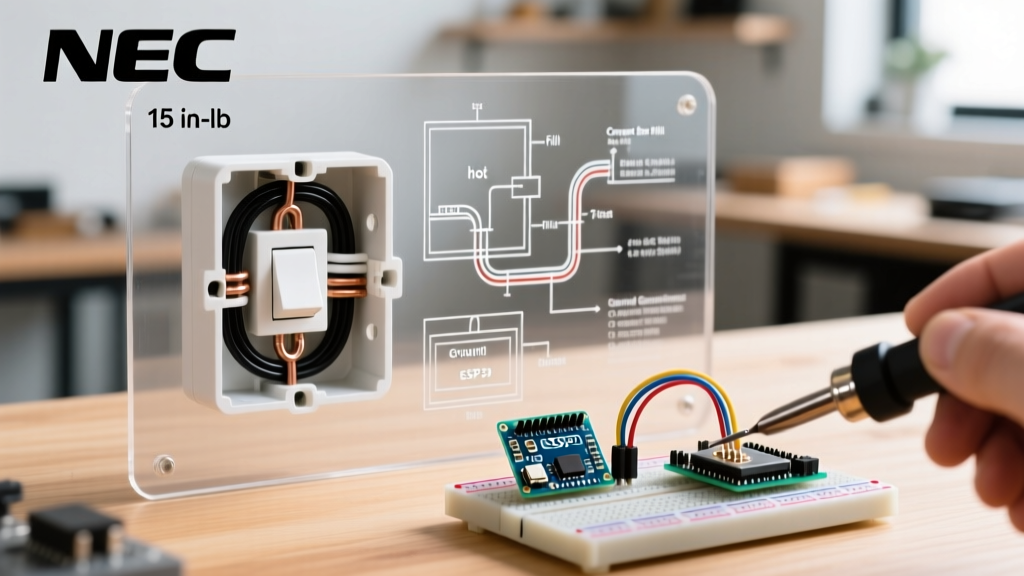
One of the most frequently ignored NEC rules by DIYers is NEC 110.14(D), which requires terminations to be torqued to the manufacturer's specified values. Loose connections cause thermal expansion and contraction, eventually leading to series arcing and electrical fires.
For the Leviton 5601 switch, the manufacturer specifies a terminal torque of 14 inch-pounds. You must use a calibrated torque screwdriver (such as the Wiha 28501) set to this exact value. Hand-tightening 'until it feels snug' is no longer acceptable under modern inspection standards and is a leading cause of residential electrical fires according to the U.S. Consumer Product Safety Commission.
AFCI Protection and Circuit Sizing
Under NEC 210.12, virtually all 120V, single-phase, 15- and 20-amp branch circuits supplying outlets or devices in living rooms, bedrooms, and hallways must be protected by an Arc-Fault Circuit Interrupter (AFCI).
When following your wiring diagram for house light switch configurations, ensure the breaker in the main panel is a Combination-Type AFCI (e.g., Square D HOM115AFIC). If you are installing a switch on a multi-wire branch circuit (MWBC), you must use a 2-pole AFCI breaker with a common trip mechanism to prevent overloading the shared neutral.
Common Code Violations in DIY Diagrams
When sourcing diagrams online, watch out for these dangerous, outdated practices:
- Switched Neutrals: Breaking the neutral instead of the hot wire. This leaves the light fixture energized at 120V even when the switch is 'off,' posing a lethal shock risk during bulb changes.
- Back-Stabbing (Push-In) Terminals: While UL-listed, push-in connections on 15A switches rely on a tiny internal spring that can lose tension over time. The NEC and professional best practices strongly mandate using the side-screw terminals with a torque screwdriver.
- Missing Box Clamps: NM-B (Romex) cable must be secured within 8 inches of the box (NEC 334.30) and protected by a cable connector where it enters the box to prevent the metal edges from slicing the sheathing.
Final Inspection and Safety Verification
Before energizing the circuit, perform a visual inspection. Ensure no bare copper is visible outside the terminal connections, all grounds are securely pigtailed, and the wires are neatly folded into the back of the box using a 'Z-fold' technique to prevent pinching. Once the breaker is energized, test the circuit with an AFCI receptacle tester to confirm the breaker trips appropriately under simulated arc-fault conditions. Adhering strictly to these NEC guidelines ensures your installation is not only functional but fundamentally safe for decades to come.