
The Reality of Plug-In Solar: Why Shared Outlets Are a Fire Hazard
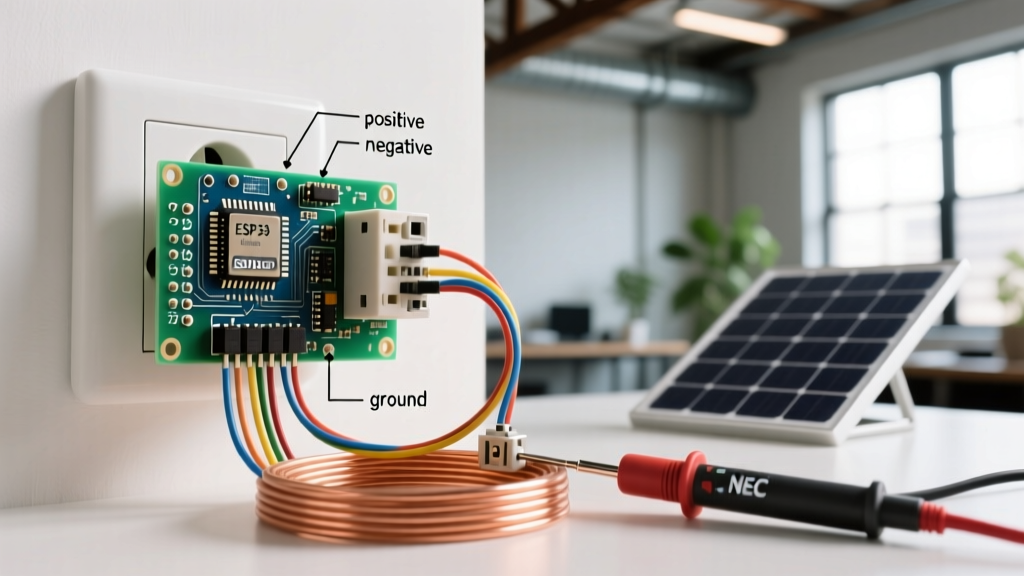
The plug-in solar market—often referred to as balcony solar or patio solar—has exploded in 2026. With the rise of ultra-efficient 400W to 800W bifacial modules and microinverters like the Hoymiles HMS-800 and Enphase IQ8A, homeowners are eager to simply plug a solar panel into an electrical outlet and watch their meter spin backward. However, the phrase "solar panel to electrical outlet" is frequently misunderstood by DIYers, leading to severe code violations and fire risks.
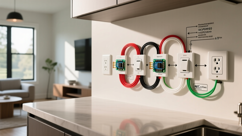
Plugging a grid-tied microinverter into a standard, shared 15A bedroom or living room receptacle is a direct violation of the National Electrical Code (NEC). When a microinverter pushes current backward through a shared circuit, it can overload the neutral busbar, overheat standard residential receptacles not rated for continuous backfeed, and create arc-fault conditions. To legally and safely connect a solar panel to an electrical outlet, you must install a dedicated, properly sized receptacle circuit governed by NEC Article 690 and Article 705.
NEC Compliance: Article 705 and the Dedicated Circuit Rule
According to the National Fire Protection Association (NFPA), NEC Article 705.12 dictates how distributed generation sources (like solar) must connect to the premises wiring. For a plug-in microinverter setup, the outlet must be on a dedicated circuit. This means no other appliances, lights, or receptacles can share the breaker or the neutral line. Furthermore, the circuit must be sized to handle the continuous output of the inverter at 125% of its maximum rated current.
Expert Edge Case: The 120% Busbar Rule
If your main service panel is already near capacity, adding a solar backfeed breaker requires calculating the 120% busbar rule (NEC 705.12(B)). For a standard 200A panel with a 40A solar allowance, your dedicated solar outlet breaker must fit within this calculated margin. Always verify your panel’s busbar rating before installing the dedicated line.
Materials & Tool List (2026 Standards)
To ensure longevity and prevent thermal degradation, commercial-grade materials are mandatory for solar receptacles. Standard builder-grade outlets will melt under the continuous thermal load of solar generation.
- Breaker: 20A Single-Pole Thermal-Magnetic Breaker (e.g., Eaton BR120 or Siemens Q120). Note: Avoid AFCI/GFCI combo breakers for microinverters unless mandated by your local AHJ, as the high-frequency switching harmonics of inverters frequently cause nuisance tripping.
- Wire: 12 AWG THHN in EMT conduit (outdoor/exposed) or 12/2 NM-B Romex (indoor concealed). 10 AWG is required for long runs to mitigate voltage rise.
- Receptacle: Hubbell HBL5262 (20A Commercial Spec Grade, Tamper Resistant). Industrial grade contacts are required to handle continuous backfeed without arcing.
- Weatherproof Cover: TayMac BX100 Extra-Duty While-In-Use Cover (for outdoor installations).
- Tools: Wire strippers, torque screwdriver (calibrated to inch-pounds), non-contact voltage tester, multimeter, and fish tape.
Step-by-Step: Wiring the Dedicated Solar Receptacle
Step 1: Load Calculation and Breaker Installation
Turn off the main breaker to de-energize the panel. Identify an available slot and install your 20A single-pole breaker. A standard 15A microinverter output (like a 1500W multi-panel setup) requires a 20A breaker because solar generation is classified as a continuous load (operating for 3 hours or more). NEC 210.20(A) requires the breaker to be rated at 125% of the continuous load. Connect the 12 AWG black (hot) wire to the breaker terminal and torque it to the manufacturer’s specification (typically 35-45 in-lbs for standard load centers).
Step 2: Routing the Dedicated 12 AWG Feeder
Run the 12/2 NM-B or THHN wires from the panel to the target receptacle location. Because this is a dedicated circuit, label the breaker clearly in the panel directory: "SOLAR PV DEDICATED RECEPTACLE - DO NOT SHARE NEUTRAL." Sharing the neutral with another circuit can result in catastrophic neutral overload, as the currents will not cancel out on the busbar.
Step 3: Terminating the Heavy-Duty Receptacle
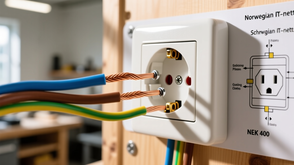
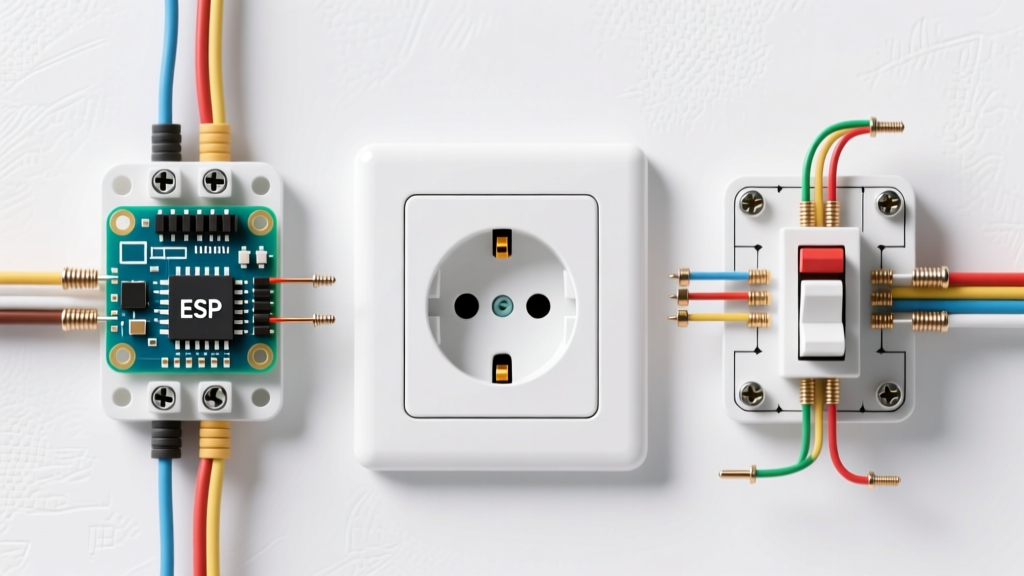
Strip the wire insulation and terminate the connections on the Hubbell HBL5262 receptacle. Never use the push-in backstab connectors. Backstab connections rely on a small spring clip that will inevitably loosen under the continuous thermal cycling of solar generation, leading to high-resistance arcing. Instead, use the screw terminals. Wrap the bare copper ground around the green grounding screw, the white neutral to the silver screw, and the black hot to the brass screw. Use a torque screwdriver set to 14 in-lbs to ensure a perfect mechanical bond.
Step 4: Weatherproofing and Microinverter Connection
If the outlet is outdoors, install the TayMac BX100 extra-duty cover. This allows the microinverter’s NEMA 5-15P or 5-20P AC cord to remain plugged in while the cover is fully closed, maintaining the weatherproof integrity of the enclosure. Plug in your microinverter AC trunk cable, restore the main breaker, and turn on the dedicated 20A solar breaker.
Voltage Drop & Wire Sizing Matrix
One of the most common failure modes in DIY solar-to-outlet installations is voltage rise. Microinverters push current into the grid, which raises the voltage at the point of interconnection. If the voltage at the receptacle exceeds the inverter’s grid-tolerance threshold (usually 126V for a 120V nominal system), the inverter will disconnect from the grid to protect utility workers, resulting in lost generation. To prevent this, you must limit voltage drop to under 1.5%.
| Run Distance (Panel to Outlet) | Max Current (Continuous) | Required Wire Gauge (Copper) | Expected Voltage Drop |
|---|---|---|---|
| Under 30 Feet | 16 Amps | 12 AWG | ~0.8% |
| 30 to 60 Feet | 16 Amps | 10 AWG | ~1.1% |
| 60 to 100 Feet | 16 Amps | 8 AWG | ~1.3% |
| Over 100 Feet | 16 Amps | 6 AWG | ~1.2% |
Note: Upsizing the wire ensures your microinverter stays synchronized with the grid even during peak noon production when grid voltage naturally swells.
Why Microinverters Trip GFCI Receptacles (And the Fix)
A frequent troubleshooting headache for DIYers wiring a solar panel to an electrical outlet is the GFCI receptacle constantly tripping. Microinverters utilize high-frequency pulse-width modulation (PWM) to synthesize the AC sine wave. This process inherently creates minor, harmless high-frequency leakage currents to ground. Standard Class A GFCI receptacles (which trip at 4-6mA of leakage) often misinterpret this high-frequency noise as a dangerous ground fault.
The Expert Fix: Do not use a GFCI receptacle at the point of connection. Instead, rely on the microinverter’s internal Ground Fault Protection (GFP), which is rigorously tested and mandated by UL 1741 standards. If your local jurisdiction strictly requires external GFCI protection for outdoor receptacles, install a GFCI circuit breaker at the main panel rather than a GFCI receptacle at the outlet. Panel-mounted GFCI breakers utilize more advanced digital signal processing (DSP) filters that can differentiate between dangerous DC ground faults and harmless inverter switching noise.
Final Inspection & Grid Interconnection
Before finalizing your installation, understand that even a simple plug-in balcony solar system requires utility notification in most municipalities. According to guidelines published by the National Renewable Energy Laboratory (NREL), connecting any generation source to the grid requires an interconnection agreement to ensure your system has anti-islanding capabilities. Modern UL 1741-SA and IEEE 1547-2018 certified microinverters handle this automatically, shutting down within milliseconds if the grid drops. Keep your microinverter’s compliance certificate and your dedicated circuit wiring diagram on hand for your local Authority Having Jurisdiction (AHJ) inspector to ensure your solar-to-outlet setup is safe, legal, and optimized for decades of production.