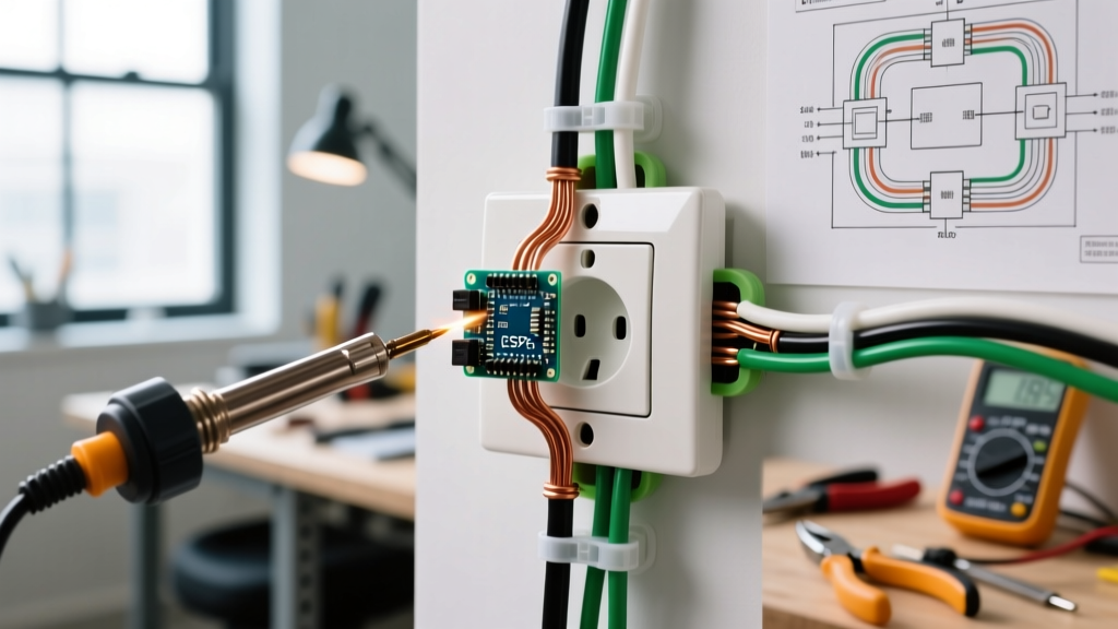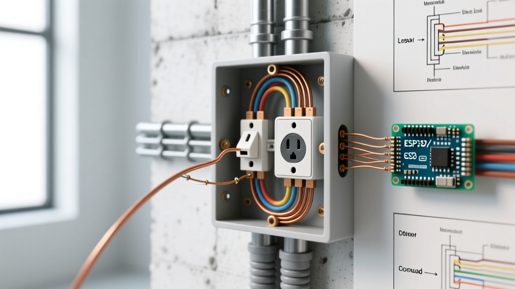

Decoding the 120V Branch Circuit Diagram
When homeowners ask why an electrical outlet is not working, the immediate instinct is often to check the breaker or swap the receptacle. However, as any seasoned electrician will tell you, randomly replacing hardware without understanding the underlying circuit topology is a recipe for recurring faults and potential fire hazards. To properly diagnose a dead receptacle, you must mentally map the physical wires to a standard 120V branch circuit wiring diagram.
In a standard North American residential wiring diagram, power originates from the panel, travels via the 'Line' (hot) conductor—typically black or red—to the brass-colored terminal on the receptacle. The current flows through the connected device and returns via the 'Neutral' conductor (white) to the silver-colored terminal, completing the circuit back to the panel. The bare copper or green wire is the 'Ground,' which connects to the green terminal and provides a safe path for fault currents. When an outlet fails, the break in this continuous loop is rarely at the receptacle itself; it is usually hidden inside a wire nut junction, a backstabbed connection, or a miswired downstream GFCI.
The Wiring Diagram Fault Matrix
Before pulling out a screwdriver, use this diagnostic matrix to match your specific symptoms to the corresponding wiring diagram fault point. This structured approach eliminates guesswork and targets the exact node of failure.
| Observed Symptom | Wiring Diagram Fault Point | Multimeter Reading (Line-to-Neutral) | Required Corrective Action |
|---|---|---|---|
| Completely dead, no voltage detected at all. | Open Hot (Line) upstream. Broken wire nut or tripped breaker. | 0.0V | Trace hot wire back to the previous junction box or panel. |
| Non-contact tester beeps, but devices won't power on. | Open Neutral upstream. The return path is severed. | 120V (no-load), drops to 0V under load. | Locate the upstream neutral wire nut and re-terminate. |
| Outlet works, but downstream outlets in the room are dead. | GFCI Line/Load reversal or failed LOAD terminal pigtail. | 120V at source, 0V at downstream. | Correct GFCI Line/Load wiring; ensure downstream wires are in LOAD terminals. |
| Top half works, bottom half is dead (or vice versa). | Split-receptacle brass tab intact or switch-loop hot wire disconnected. | 120V on one half, 0V on the other. | Break the brass fin on the hot side; verify red switched-hot wire connection. |
| Intermittent power; flickers when wall is tapped. | Backstab (push-in) terminal failure due to thermal expansion. | Fluctuates between 0V and 120V. | Move wires from backstab holes to side-screw terminals or clamp plates. |
Deep Dive: Backstab Failures vs. Clamp-Plate Terminals
One of the most frequent reasons an electrical outlet stops working after years of flawless operation is the failure of 'backstab' or push-in terminals. According to UL 498 standards, these internal spring-loaded grips are technically legal for 14 AWG copper wire. However, in real-world applications, they are a massive point of failure.
When current flows through a high-draw appliance (like a space heater or hair dryer), the receptacle heats up. The brass contacts and the copper wire expand at different rates. Over hundreds of thermal cycles, the internal spring grip weakens. Eventually, the wire creates a high-resistance connection, leading to arcing, voltage drop, and ultimately, an open circuit. If your wiring diagram shows a daisy-chained circuit where the outlet acts as a pass-through to other rooms, a single failed backstab on the neutral side will kill every outlet downstream.
Pro Tip: When replacing a failed receptacle, never use the push-in holes. Instead, use the side-screw terminals, wrapping the wire clockwise around the screw so the tightening action pulls the loop closed. For 12 AWG wire, or for a more secure connection, invest in commercial-grade receptacles like the Leviton 16252-W, which features internal clamp-plate back-wiring terminals that securely bite down on the wire without relying on a fragile spring.
GFCI Line/Load Reversals and Downstream Failures
If you are troubleshooting a kitchen, bathroom, or garage circuit, your wiring diagram must account for Ground Fault Circuit Interrupter (GFCI) protection. Under the latest 2026 NEC (National Electrical Code) guidelines, GFCI protection is strictly mandated in all damp and wet locations, as well as specific finished basement areas (NFPA 70).
A standard GFCI receptacle, such as the Leviton 8280-W, has two distinct sets of terminals: LINE and LOAD. The LINE terminals receive power from the panel. The LOAD terminals send protected power to downstream standard receptacles. A remarkably common DIY error is wiring the incoming power to the LOAD terminals and the downstream wires to the LINE terminals.
The Result: The GFCI itself might appear to work, and it will even reset. However, the internal sensing coil is now bypassing the downstream circuit. If a ground fault occurs downstream, the GFCI will not trip, creating a lethal shock hazard. Furthermore, if the internal load relay fails due to this reverse-stress, the downstream outlets will permanently lose power while the GFCI face remains live. Always use a multimeter to identify the incoming hot/neutral pair before connecting them to the LINE terminals.
The Split-Receptacle (Half-Hot) Tab Trap
In living rooms and bedrooms, wiring diagrams frequently utilize split-receptacles. This setup involves one half of the outlet being constantly hot, while the other half is controlled by a wall switch. This is achieved using a 3-wire cable (Black, Red, White, Bare) where the black wire is the constant hot, and the red wire is the switched hot returning from the wall switch.
To make this work, the manufacturer installs a small brass connecting tab (fin) between the top and bottom hot (brass) screws. The installer must use needle-nose pliers to snap this tab off, isolating the top and bottom halves.
Why outlets fail here: When a homeowner replaces an old half-hot outlet and forgets to break this brass tab, the switched hot and constant hot are shorted together on the brass side. This will usually cause the breaker to trip immediately. Conversely, if they mistakenly break the silver (neutral) tab instead of the brass one, the circuit will appear to work but will create an unbalanced neutral return path, potentially overloading the shared neutral wire and creating a severe fire hazard.
Step-by-Step Multimeter Tracing Protocol
To definitively answer why your electrical outlet is not working, follow this precise tracing protocol using a reliable True-RMS multimeter like the Klein Tools MM400 or Fluke 117. Never rely solely on cheap neon test lights or non-contact voltage pens for final diagnostics, as they can read 'phantom voltage' from adjacent wires.
- Verify Panel Power: Confirm the breaker is fully in the ON position. If it is tripped, it will sit in the middle position. Push it firmly to OFF, then to ON.
- Test Receptacle Face: Insert multimeter probes into the hot (short slot) and neutral (long slot). A healthy circuit should read between 114V and 126V. If you read 0V, proceed to step 3.
- Test Hot-to-Ground: Move the neutral probe to the ground (U-shaped slot). If you now read 120V, you have an Open Neutral. The hot wire is intact, but the white wire is disconnected somewhere upstream.
- Test Neutral-to-Ground: Place one probe on neutral and one on ground. You should read less than 2V. If you read 120V here, you have a bootleg ground or a reversed hot/neutral upstream.
- Remove and Inspect: Turn off the breaker at the panel. Lock out and tag out the panel if possible, adhering to OSHA electrical safety standards. Unscrew the receptacle and pull it out. Inspect for melted insulation, broken wire nuts, or loose backstabbed wires.
- Continuity Check: With the power OFF, use the multimeter's continuity setting (the diode symbol) to test the white wires bundled in the back of the box. If the wire nut is loose, the meter will not beep, confirming the open neutral fault.
Safety and Code Compliance
Troubleshooting electrical wiring diagrams requires respect for the lethal energy present in a 120V branch circuit. According to the Electrical Safety Foundation International (ESFI), electrical receptacles are involved in thousands of residential fires annually, largely due to loose connections and degraded terminals. If your multimeter testing reveals melted wire insulation, scorch marks on the drywall, or a burning odor, do not simply replace the outlet. The circuit has experienced a high-resistance thermal event, and the affected wires must be cut back to bare, clean copper and re-terminated using properly rated wire connectors or Wago lever nuts. When in doubt, consult a licensed master electrician to ensure your home's wiring diagram remains safe, functional, and fully compliant with modern electrical codes.