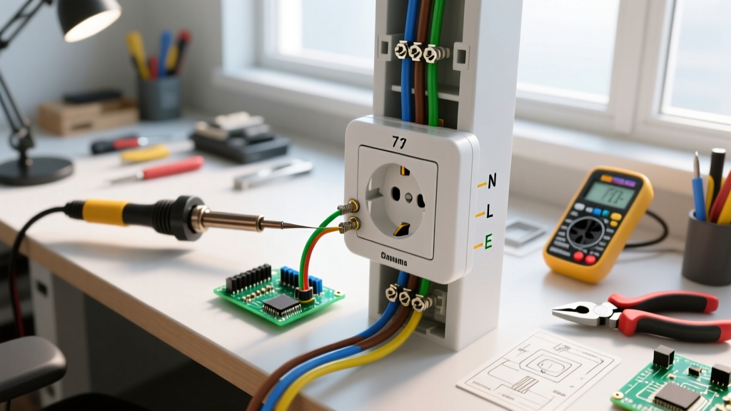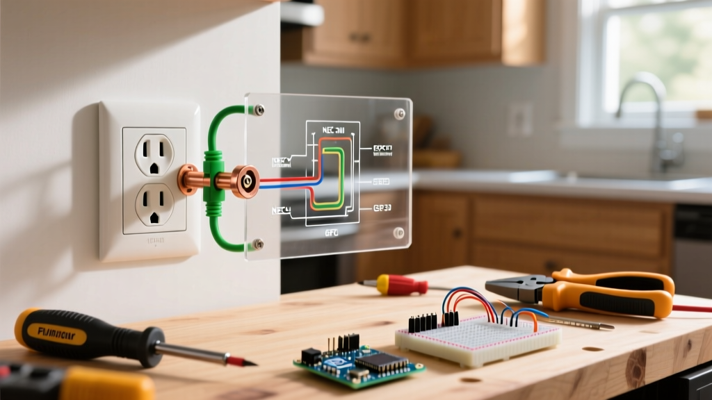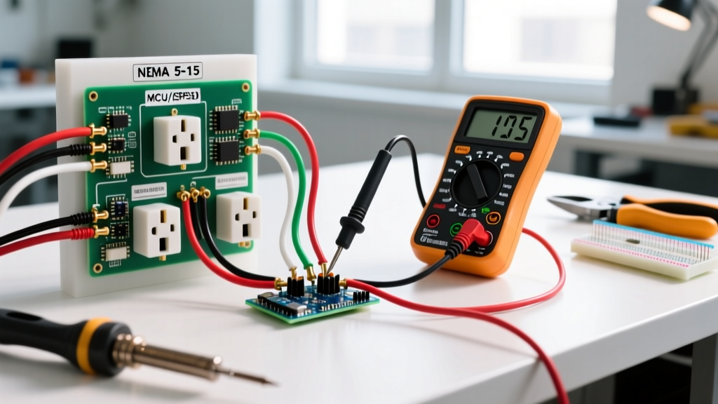

The Critical Role of a Wiring Diagram for Plug Diagnostics
In the field of electrical maintenance and DIY troubleshooting, a standard receptacle tester only tells half the story. To truly diagnose intermittent faults, voltage drops, or internal cord failures, you must understand the underlying architecture of the connection. Consulting a wiring diagram for plug configurations allows technicians and advanced DIYers to map terminal assignments, verify polarity, and isolate ground faults before they escalate into equipment damage or fire hazards.
As of 2026, the proliferation of smart appliances and high-draw EV charging cords has made rigorous plug inspection more critical than ever. This guide transitions beyond basic plug-in testers, utilizing digital multimeters (DMMs) and anatomical diagrams to perform forensic-level inspections on standard NEMA 5-15P and heavy-duty NEMA 5-20P attachment plugs.
Deconstructing the NEMA 5-15P Wiring Diagram for Plug Terminals
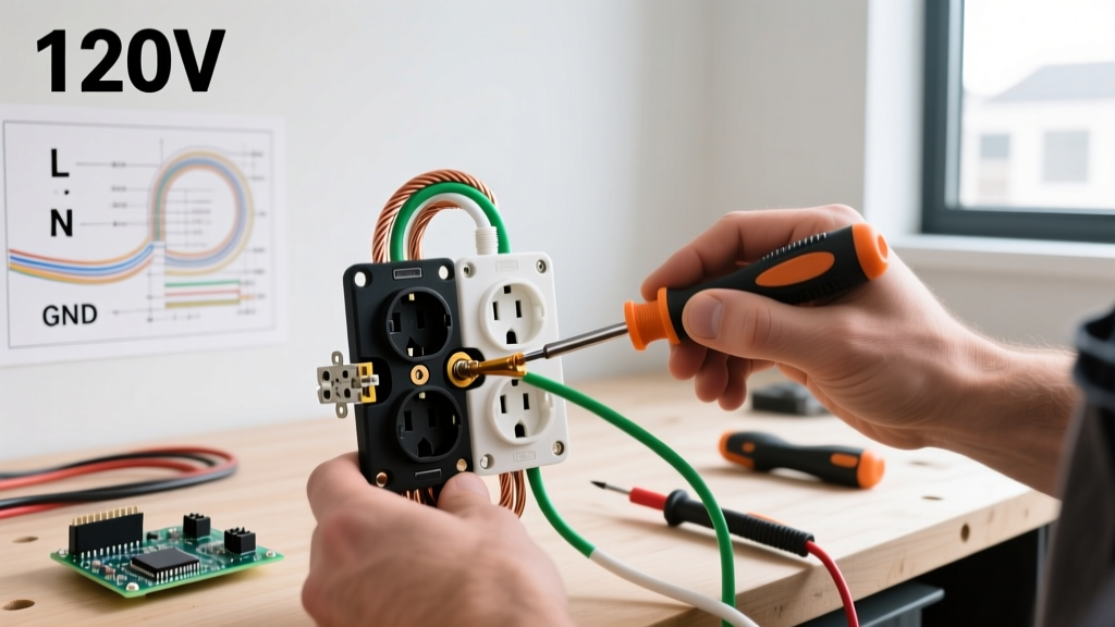
Before applying power or testing continuity, you must internalize the standard North American 15-ampere, 125-volt plug layout. The physical wiring diagram for a NEMA 5-15P plug dictates three distinct termination points, each governed by strict color-coding and dimensional standards outlined by the National Electrical Manufacturers Association (NEMA).
Terminal Mapping and Torque Specifications
- Brass Terminal (Hot/Line): Connects to the black (or red) insulated wire. Terminates to the shorter, narrower vertical blade. This carries the 120V alternating current from the breaker panel.
- Silver Terminal (Neutral): Connects to the white insulated wire. Terminates to the longer, wider vertical blade. This completes the circuit back to the transformer.
- Green Terminal (Ground): Connects to the bare copper or green insulated wire. Terminates to the U-shaped grounding pin. This provides a low-impedance fault path.
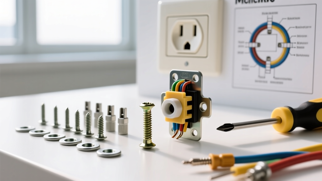
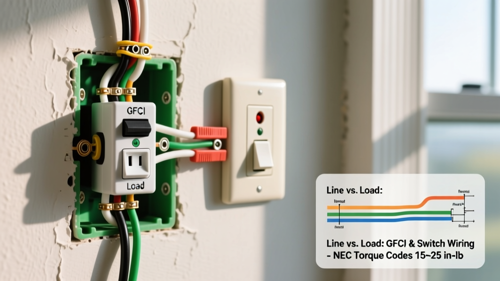
NEC 110.14(D) Compliance Note: As enforced in the 2023 and 2026 NEC cycles, terminal screws on listed attachment plugs (such as the Leviton 5266-S or Pass & Seymour 5266X) must be tightened to the manufacturer's specified torque. For standard 14 AWG and 12 AWG wiring, this typically requires 14 in-lbs (1.6 Nm) of torque. Using a calibrated torque screwdriver like the Klein Tools 69064 prevents loose connections that cause thermal arcing.
Pre-Test Visual and Mechanical Inspection Checklist
Electrical testing is futile if the physical integrity of the plug is compromised. Use the wiring diagram for plug anatomy to inspect the following mechanical failure points:
- Cord Grip and Strain Relief: The internal cord clamp must secure the outer jacket of the cable, not just the individual insulated conductors. If the jacket can be pulled out more than 1/16th of an inch, the strain relief has failed, risking a short circuit at the brass or silver terminals.
- Blade Pitting and Oxidation: Inspect the brass and silver blades for black carbon tracking or pitting. Severe arcing degrades the metal, increasing contact resistance. A healthy blade should show uniform wear marks from the receptacle wipers.
- Wire Dress and Loop Direction: When opening a replacement plug housing, verify that the wire loops clockwise around the terminal screws. Counter-clockwise loops will be pushed out from under the screw head as it is tightened, reducing the contact surface area by up to 50%.
- Insulation Clearance: Ensure no bare copper is exposed outside the terminal cup, and that the outer wire insulation is not pinched under the screw head, which can cause a slow ground fault over time.
Electrical Testing Matrix: Multimeter Readings vs. Wiring Faults
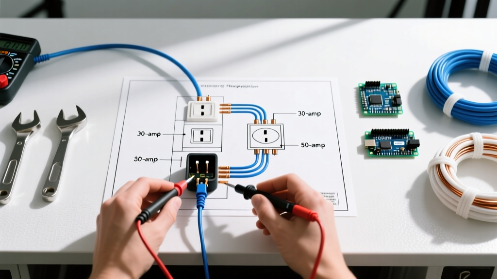
When a plug-in circuit analyzer (like the Klein Tools RT250, currently retailing around $35) indicates a fault, you must use a DMM to verify the exact nature of the wiring error. Set your multimeter (e.g., Fluke 117 or Ideal 36-164) to AC Voltage (V~) and use the blade faces of the unplugged cord's female receptacle end, or probe the male plug blades using specialized breakout adapters if testing live.
| Fault Condition | Hot-to-Neutral Reading | Hot-to-Ground Reading | Neutral-to-Ground Reading | Root Cause per Wiring Diagram |
|---|---|---|---|---|
| Normal Operation | 118V - 122V | 118V - 122V | 0V - 2V | Correct terminal mapping and low-impedance ground path. |
| Open Ground | 120V | 0V | 0V | Green terminal wire severed, or ground pin broken off inside housing. |
| Reversed Polarity | 120V | 0V - 2V | 118V - 122V | Black and white wires swapped on brass and silver screws. |
| Open Neutral | 0V | 120V | 0V | Silver terminal screw loose; white wire pulled from termination. |
| Hot/Ground Reversed | 120V | 0V | 120V | Black wire on green screw; bare wire on brass screw. EXTREME SHOCK HAZARD. |
Step-by-Step Continuity Testing (Dead Circuit Only)
If you are inspecting a detached replacement cord or an unpowered appliance plug, voltage testing is impossible. Instead, use the continuity setting (Ω) on your DMM. Warning: Never perform continuity testing on a live circuit; it will blow the multimeter's internal fuse and pose an arc flash risk.
- Prepare the Probes: Touch the red and black probes together to verify the DMM reads near 0.0Ω and emits a tone.
- Test Hot Continuity: Place one probe on the shorter (brass/hot) blade of the male plug, and the other on the corresponding brass-colored screw or terminal inside the female connector (or appliance switch). Reading should be <0.5Ω.
- Test Neutral Continuity: Move the probe to the wider (silver/neutral) blade. Verify the continuous path to the silver terminal.
- Test Ground Continuity: Probe the U-shaped ground pin and the grounding lug on the appliance chassis or the ground terminal of the female receptacle.
- Check for Shorts: Place probes across the Hot and Neutral blades. The reading must be 'OL' (Open Loop). If it reads near 0Ω, the cord has an internal dead short and must be destroyed and replaced immediately.
Edge Cases: Troubleshooting Industrial and High-Amperage Plugs
While the NEMA 5-15P is ubiquitous, industrial environments frequently utilize twist-lock connectors like the NEMA L6-30 (30A, 250V, 2-Pole, 3-Wire Ground). The wiring diagram for plug configurations in the L6 series eliminates the neutral conductor entirely, replacing it with a second hot leg (Phase B or Y-phase).
When inspecting an L6-30 plug (such as the Hubbell HBL2621BK):
- X and Y Terminals: Both brass terminals carry 120V relative to ground, but 250V relative to each other. Reversing X and Y does not affect the operation of purely resistive loads (like heaters), but can cause severe damage to 3-phase motors or sensitive inverter boards in modern CNC equipment.
- Locking Blade Wear: Inspect the curved locking blades for deformation. If the plug requires excessive rotational force to lock into the receptacle, the internal brass wipers in the receptacle are likely fatigued, which will cause localized heating at the plug interface under a continuous 24A load.
NEC Compliance and When to Replace
According to the OSHA 1910.303 standard for electrical equipment inspection, all attachment plugs and flexible cords must be maintained free from damage, splices, and exposed conductors. Furthermore, the NFPA electrical safety guidelines strongly advise against 'piggybacking' or repairing severed heavy-duty cords with standard electrical tape or wire nuts inside a plug housing.
Replace the plug immediately if:
- The plug housing is cracked, melted, or shows brown thermal discoloration around the blade slots.
- The internal fiber or paper separator between the brass and silver terminals is missing or degraded (this prevents conductive debris from bridging the terminals).
- The cord utilizes 'push-in' or 'back-stab' terminations rather than screw-loop terminations. While back-stab connections are legal in some wall receptacles, they are highly prone to failure in high-vibration environments common with portable appliance plugs.
Mastering the wiring diagram for plug diagnostics transforms you from a parts-changer into a true electrical troubleshooter. By combining mechanical inspection with precise DMM voltage and continuity matrices, you ensure that every connection meets modern safety standards, protecting both the end-user and the sensitive 2026-era electronics they power.