
Electric Dryer Power Outlet: Inspection and Testing Protocol
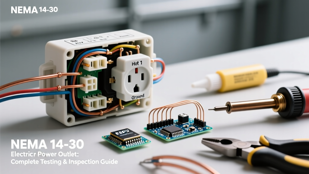
An electric dryer power outlet handles a massive continuous electrical load, typically drawing 24 to 30 amps at 240 volts. Because these circuits operate near their maximum rated capacity for hours at a time, any degradation in the receptacle, wiring, or terminations can lead to thermal runaway, melted faceplates, or catastrophic electrical fires. According to the U.S. Fire Administration, failure of electrical wiring and outlets is a leading cause of residential dryer fires. This comprehensive guide provides a professional-grade inspection and testing workflow for the modern NEMA 14-30R electric dryer power outlet.
CRITICAL SAFETY WARNING: Testing live 240V circuits carries a severe risk of arc flash and fatal electrocution. You must use a CAT III 600V (or higher) rated digital multimeter (DMM), wear ANSI-rated safety glasses, and ensure your hands and work area are completely dry. If you are not comfortable working around live split-phase panels, hire a licensed electrician.
Identifying Your Receptacle Configuration
Before testing, you must identify the physical configuration of the outlet. The National Electrical Code (NEC) mandated a shift from 3-prong to 4-prong dryer outlets in 1996 to separate the neutral and equipment grounding conductors. However, older homes still frequently feature the obsolete 3-prong setup.
| Feature | NEMA 10-30R (Obsolete 3-Prong) | NEMA 14-30R (Modern 4-Prong) |
|---|---|---|
| Poles / Wires | 3 Poles, 3 Wires (Hot, Hot, Neutral) | 3 Poles, 4 Wires (Hot, Hot, Neutral, Ground) |
| Voltage / Amperage | 125/250V, 30A | 125/250V, 30A |
| Grounding Path | Neutral acts as ground (Dangerous) | Dedicated Equipment Grounding Conductor (EGC) |
| Code Status (2026) | Grandfathered for existing installs; illegal for new | Required for all new installations and replacements |
Note: If you have a NEMA 10-30R, the National Fire Protection Association (NFPA) strongly recommends upgrading to a 4-wire circuit with a NEMA 14-30R to eliminate the shock hazard caused by a floating or broken neutral.
Step-by-Step Live Voltage Testing Matrix
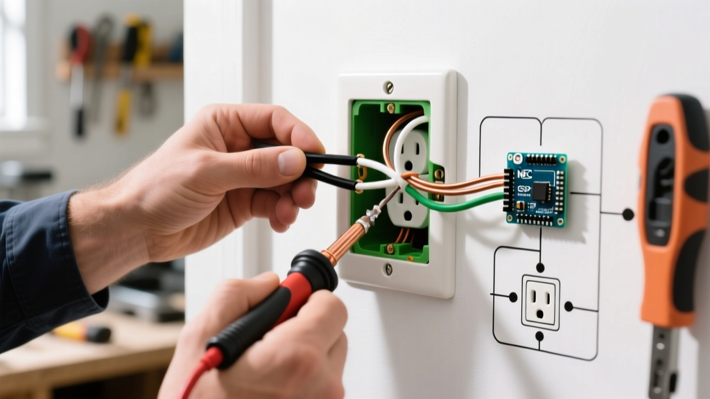
To verify the health of the circuit, you must test the voltage at the receptacle slots under no-load conditions. Set your CAT III multimeter to AC Voltage (V~). Insert the probes firmly into the slots to ensure solid contact with the internal brass busbars.
The NEMA 14-30R Voltage Diagnostic Matrix
Use this matrix to diagnose specific wiring faults based on your multimeter readings. The standard tolerance for residential voltage is ±5%.
| Test Points | Expected Reading | Diagnostic Meaning / Fault Indication |
|---|---|---|
| L1 (X) to L2 (Y) | 240V (228V - 252V) | Confirms both hot legs are present. If 0V, breaker is tripped or open. If 120V, one hot leg is dead. |
| L1 (X) to Neutral (W) | 120V (114V - 126V) | Confirms L1 and Neutral integrity. Low voltage indicates high resistance on the neutral bus. |
| L2 (Y) to Neutral (W) | 120V (114V - 126V) | Confirms L2 and Neutral integrity. |
| L1 (X) to Ground (G) | 120V | Verifies the grounding path back to the panel is intact. |
| L2 (Y) to Ground (G) | 120V | Verifies the grounding path back to the panel is intact. |
| Neutral (W) to Ground (G) | < 1.5V (Ideally 0V) | Critical Test: If > 2V, you have a 'floating neutral' or high-resistance neutral connection in the panel or upstream junction box. |
Physical Inspection: Spotting Thermal and Mechanical Failures
Voltage testing only tells half the story. A circuit can show perfect 240V under no-load conditions but completely fail or catch fire when the dryer draws 25 amps. You must physically inspect the receptacle.
1. Disconnect Power and Extract the Receptacle
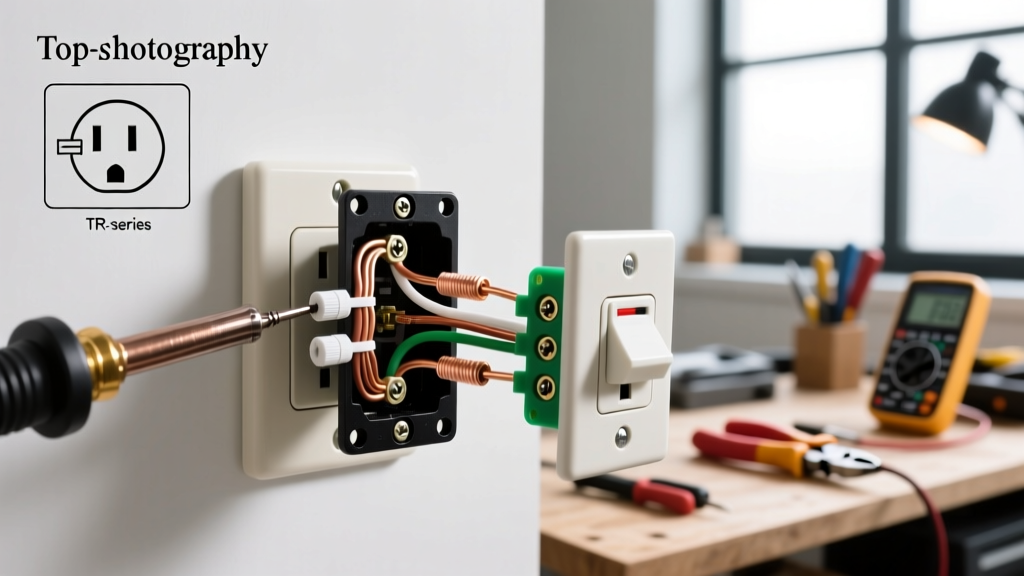
Turn off the 30A double-pole breaker at the main service panel. Verify the power is dead using a non-contact voltage tester (NCVT) and your multimeter. Remove the single center screw holding the faceplate, then remove the two terminal screws securing the receptacle yoke to the electrical box. Gently pull the receptacle out.
2. Inspect for Thermal Damage
- Faceplate and Yoke Discoloration: Look for brown, black, or melted plastic around the L1, L2, or Neutral slots. This indicates 'thermal runaway' caused by a loose internal busbar grip or high-resistance wire termination.
- Wire Insulation: Check the THHN/THWN-2 wire insulation where it enters the terminal screws. If the insulation is brittle, cracked, or pulled back more than 1/16th of an inch from the terminal, the wire has been subjected to excessive heat.
- Receptacle Grip Tension: Insert the male dryer plug into the receptacle. It should require significant force to insert and remove. If it slides in easily, the internal brass wipers have lost their spring tension and the receptacle must be replaced immediately.
3. Verify Wire Gauge and Termination Torque
A 30-amp circuit strictly requires a minimum of 10 AWG copper wire. Using 12 AWG is a severe fire hazard and an NEC violation. Furthermore, how the wire is terminated matters immensely:
- No Backstabbing: 30A receptacles do not use push-in backstab connectors. All wires must be wrapped clockwise around the screw terminals or secured via screw-clamp plates.
- Torque Specifications: According to NEC 110.14(D), terminations must be torqued to the manufacturer's specifications. For standard Leviton or Pass & Seymour NEMA 14-30R receptacles, the screw terminals typically require 14 to 18 inch-pounds (in-lbs) of torque. Use an insulated torque screwdriver to verify. Under-torquing causes arcing; over-torquing strips the brass threads or shears the screw.
Edge Cases and Advanced Troubleshooting
When inspecting electric dryer power outlets, electricians frequently encounter specific edge cases that cause intermittent appliance failures.
The 'Bootleg Ground' on Converted 4-Prong Outlets
In older homes, DIYers sometimes replace a 3-prong NEMA 10-30R with a 4-prong NEMA 14-30R without pulling a new 4-wire cable. To make the new plug fit, they illegally jumper the Neutral (W) and Ground (G) terminals at the receptacle. This is lethal. If the neutral wire breaks upstream, the entire metal chassis of the dryer becomes energized at 120V. Always verify that the Ground terminal connects to a dedicated bare copper or green insulated wire returning to the panel's ground bus.
Aluminum Wiring Oxidation
Some homes built in the 1960s and 70s used 8 AWG aluminum wire for 30A dryer circuits. Aluminum creeps and oxidizes over time, leading to high-resistance connections. If you find aluminum wire:
- The receptacle must be explicitly rated CO/ALR (Copper/Aluminum Revised), such as the Leviton 278-S00.
- The wire ends must be cleaned with a wire brush and coated with an anti-oxidant compound like Noalox or Penetrox-E.
- Terminals must be re-torqued annually, as aluminum 'cold flows' and loosens under pressure.
Neutral Float and Control Board Destruction
Modern electric dryers use sensitive 120V electronic control boards. If the Neutral (W) connection at the outlet or panel is loose, the 120V loads become wired in series across the 240V supply. Depending on the resistance of the dryer's motor and timer, the control board may receive 180V+ instead of 120V, instantly destroying the PCB. If a homeowner reports repeated control board failures, test the Neutral-to-Ground voltage under load using a clamp meter; a reading above 3V under load confirms a failing neutral.
When to Replace and Cost Expectations
Receptacles are mechanical wear items. The NFPA recommends replacing any outlet showing physical degradation. If your NEMA 14-30R fails any of the physical or voltage tests above, replacement is mandatory.
2026 Replacement Cost Breakdown
- DIY Parts Cost: A high-quality, commercial-grade NEMA 14-30R receptacle (e.g., Pass & Seymour 2620 or Leviton 278-S00) costs between $18 and $28. Avoid $8 residential-grade builder packs; their internal busbars cannot handle continuous 30A dryer loads.
- Professional Electrician Cost: Hiring a licensed electrician to diagnose, replace the receptacle, and verify panel terminations typically costs between $175 and $275, depending on regional labor rates and accessibility.
- Circuit Upgrade (3-Prong to 4-Prong): If you need to pull a new 10/3 NM-B (Romex) or THHN in conduit to upgrade from NEMA 10-30 to 14-30, expect to pay $400 to $850 depending on the distance from the panel and drywall repair requirements.
Final Verification
After replacing or servicing the electric dryer power outlet, perform a final live voltage test using the matrix above. Plug in the dryer, start a high-heat timed dry cycle, and use an infrared thermal camera or non-contact infrared thermometer to scan the receptacle faceplate. After 15 minutes of operation, the outlet temperature should not exceed ambient room temperature by more than 15°F (8°C). Any localized hot spots indicate a failing internal connection that requires immediate attention.