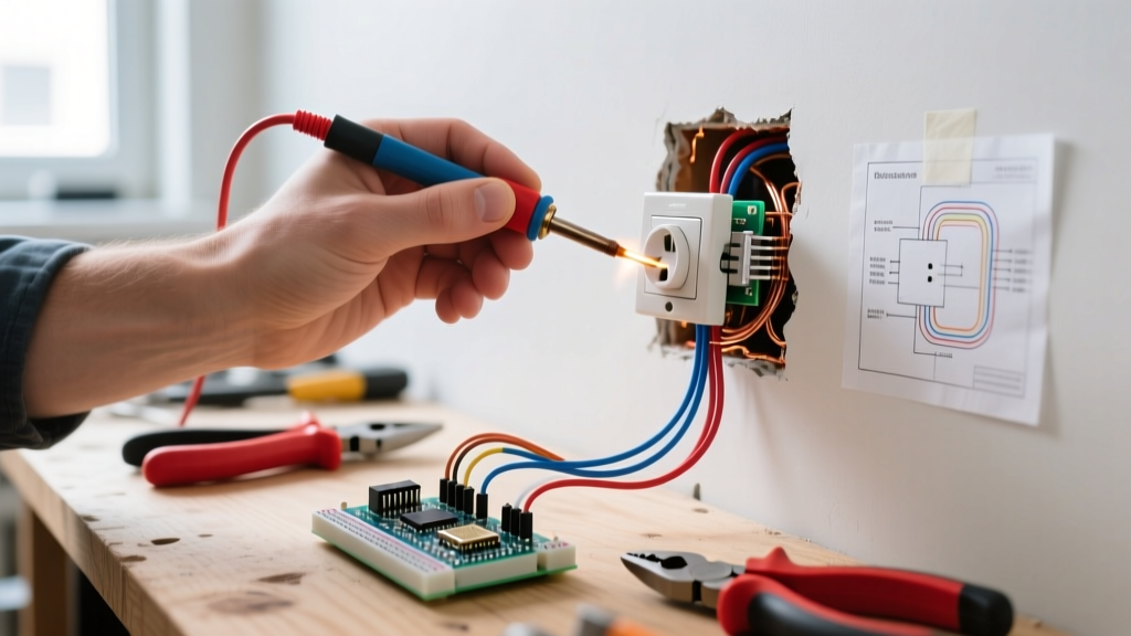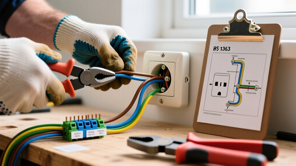

The Anatomy of a BS 1363 British Electrical Outlet
The standard British electrical outlet, globally recognized as the Type G plug and socket system, is governed by the rigorous BS 1363 standard. Unlike North American NEMA 5-15 receptacles, the UK system integrates a 13-amp fuse directly into the plug, allowing the use of thinner, more flexible appliance cords while protecting the branch circuit via a 32-amp breaker at the consumer unit. For DIYers and expats navigating UK electrical systems, understanding the unique topology of British wiring—specifically the Ring Final Circuit—is critical before picking up a screwdriver.
This beginner installation tutorial focuses on replacing or installing a standard 13A switched socket (such as the widely used MK Logic Plus K9901 WHI) on an existing 2.5mm² Twin & Earth ring main or radial circuit. We will cover harmonized cable colors, precise termination techniques, and the legal safety frameworks governing UK electrical work in 2026.
UK Legal and Safety Prerequisites (Part P)
Before touching any wiring, you must understand the UK Building Regulations Part P. According to the Electrical Safety First guidelines, like-for-like replacement of a damaged socket or adding a new socket to an existing ring main in a non-special location (e.g., a standard living room or bedroom) is classified as non-notifiable work. You do not need to inform your local building control authority. However, installing a completely new circuit, or working in 'special locations' like bathrooms or outdoors, requires notification and sign-off by a certified competent person.
Safety Imperative: Never rely solely on a wall switch to isolate power. Always isolate the circuit at the Consumer Unit (fusebox) using the relevant MCB or RCBO, and apply a physical lock-off device to prevent accidental re-energization.
Essential Tools and Material Costs (2026 Pricing)
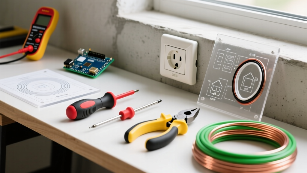
Professional-grade tools are non-negotiable when terminating 2.5mm² solid copper conductors. Cheap screwdrivers will cam out, damaging the brass terminal screws and creating high-resistance hot spots.
- VDE Insulated Screwdrivers (1000V rated): Wera or Wiha Pozidriv #2. (£12 - £18)
- Voltage Tester: Fluke T5-600 or a dedicated CAT III/IV voltage indicator and proving unit. (£45 - £120)
- Wire Strippers: Knipex Automatic or Jokari No. 12. (£25 - £35)
- Torque Screwdriver: Calibrated to 1.5 Nm (critical for BS 1363 terminals). (£40 - £60)
- Earth Sleeving: Green/Yellow PVC sleeving (4mm diameter). Modern 6242Y cable features a bare CPC (earth) that must be sleeved. (£4 per roll)
- The Socket: MK Logic Plus 13A Switched Socket or Schneider Electric Lisse Deco. (£6 - £9 per unit)
UK Harmonized Cable Colors and Terminal Mapping
In 2004, the UK harmonized its fixed wiring colors with European standards (IEC 60446). If you are working in a home built or rewired before 2006, you may encounter the old color codes. The Institution of Engineering and Technology (IET) BS 7671 wiring regulations mandate strict adherence to the new colors for all new installations.
| Function | Post-2004 Harmonized Color | Pre-2004 Legacy Color | Terminal Marking |
|---|---|---|---|
| Line (Live) | Brown | Red | L |
| Neutral | Blue | Black | N |
| Earth (CPC) | Green & Yellow (or Bare + Sleeve) | Green (or Bare) | E or ⏚ |
Step-by-Step Installation Tutorial
Step 1: Isolation and Verification
Switch off the 32A MCB or RCBO protecting the ring final circuit at the consumer unit. Insert your lock-off device. Use your approved voltage indicator to test between Line and Neutral, Line and Earth, and Neutral and Earth at the existing socket. Prove the tester on a known live source before and after testing to ensure the device hasn't failed silently.
Step 2: Cable Preparation and Earth Sleeving
Unscrew the existing faceplate and gently pull it forward. In a UK Ring Final Circuit, you will typically see two 2.5mm² Twin & Earth cables entering the backbox (representing the incoming and outgoing legs of the ring).
Strip the outer grey PVC sheath back to within 15mm of the backbox entry. Strip exactly 12mm to 14mm of insulation from the Brown and Blue solid copper cores. Slide a 25mm length of green/yellow PVC sleeving over the bare copper Circuit Protective Conductor (CPC) and push it all the way down to the sheath.
Step 3: Managing the Ring Main Termination
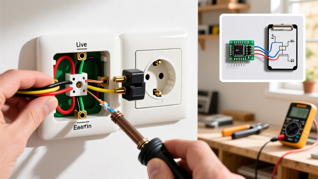
This is where most beginners fail. You must terminate two Brown wires into the 'L' terminal, two Blue wires into the 'N' terminal, and two Earth wires into the 'E' terminal.
Do not twist the solid copper strands together aggressively, as this can cause them to splay and short against the backbox. Neatly fold the two 12mm bare ends together so they sit flush. If the copper is heavily oxidized or frayed from previous work, snip them back to clean copper. For ultimate compliance, use a twin bootlace ferrule crimped over the two solid cores, though neatly folded bare solid copper is standard practice in UK domestic wiring if the terminal clamp is large enough.
Step 4: Termination Sequence and Torque
Always wire in this specific order to maintain safety grounding continuity during the process:
- Earth (E): Insert the sleeved CPCs into the top center terminal. Tighten to 1.5 Nm.
- Neutral (N): Insert the Blue wires into the left terminal (marked N). Tighten to 1.5 Nm.
- Line (L): Insert the Brown wires into the right terminal (marked L, usually near the switch). Tighten to 1.5 Nm.
Critical Check: Give each wire a firm 'tug test'. If a wire pulls out, the terminal screw was not seated correctly, or the insulation was accidentally clamped under the screw head, which will cause an open circuit or arcing.
Step 5: Backbox Dressing and Mounting
Carefully fold the cables into the 35mm deep steel or dry-lining backbox. Ensure the green/yellow earth sleeving is visible and that no bare copper is exposed outside the terminals. Route the cables to the sides of the backbox to avoid pinching them behind the faceplate plasterboard claws. Secure the faceplate using the provided M3.5 machine screws, ensuring the integrated spirit level (if present on premium models) is perfectly horizontal.
Critical Edge Cases and Troubleshooting
The 'Spur' Limitation
If you are adding a new socket to an existing ring, UK wiring regulations (BS 7671) strictly limit the number of unfused spurs. You can only add one single or one double socket as an unfused spur from an existing point on the ring. If you need to add multiple sockets in a new extension, you must run a new radial circuit from the consumer unit or fuse the spur with a 13A switched fused connection unit (FCU).
Over-Tightening Terminal Screws
Beginners often use maximum force on terminal screws. The brass terminal blocks in standard 13A sockets will strip at around 2.5 Nm. If you over-tighten to 2.0 Nm or higher, you risk crushing the 2.5mm² solid copper, reducing its cross-sectional area. This increases electrical resistance, leading to localized heating (thermal runaway) under heavy continuous loads like portable heaters or EV chargers.
Reversed Polarity Faults
If you accidentally swap the Brown and Blue wires, the socket will still function because AC current alternates. However, this creates a lethal reversed polarity fault. The single-pole switch on the faceplate will now isolate the Neutral instead of the Line. The appliance will turn off, but its internal components will remain energized at 230V relative to earth, posing a severe shock hazard if a user attempts to repair the appliance. Always verify polarity with a dedicated UK socket tester (e.g., Martindale EZ150) after energizing the circuit.
For complex installations or if you are unsure about the integrity of your home's earthing arrangement (specifically the External Earth Loop Impedance, Ze), consult a registered electrician certified by a body like the NICEIC or NAPIT to perform a full Electrical Installation Condition Report (EICR).