
The Hidden Dangers of a Broken Electrical Outlet
A broken electrical outlet is not merely a cosmetic nuisance; it is a primary ignition point for residential fires. According to the U.S. Consumer Product Safety Commission (CPSC), electrical receptacles are involved in over 5,000 residential fires annually. When the internal brass contacts lose their tension, or when builder-grade push-in connections degrade from thermal cycling, the resulting electrical arcing can generate temperatures exceeding 1,500°F (815°C). If you notice plugs falling out, discolored faceplates, or a buzzing sound, immediate replacement is mandatory. This comprehensive upgrade guide will walk you through diagnosing the failure, selecting commercial-grade replacement materials, and executing a code-compliant termination.
Recognizing the 5 Critical Failure Modes
Before pulling out your tools, confirm that your receptacle is actually failing. Here are the definitive symptoms of a broken electrical outlet:
- Loss of Plug Retention (Brass Fatigue): If a standard two-prong or three-prong plug slides into the socket without resistance or falls out under the weight of its own cord, the internal brass wipers have permanently deformed. This creates a high-resistance connection that generates severe heat.
- Thermal Discoloration: Brown or black scorch marks around the blade slots indicate active arcing. The polycarbonate faceplate may also feel warm to the touch or emit a faint, acrid 'fishy' odor (the smell of melting PVC insulation).
- Backstab Connection Failure: If an outlet suddenly goes dead, but the breaker hasn't tripped, the failure is often upstream. Builder-grade outlets frequently use push-in 'backstab' terminals. Over years of thermal expansion and contraction, the wire oxidizes and loses contact inside the spring-loaded clamp.
- Physical Cracking: Impact damage from heavy furniture or vacuum cleaners can fracture the internal yoke, misaligning the contacts and creating a shock hazard.
- Ghost Voltage or Buzzing: A faint hum or a tingling sensation when touching the faceplate screw indicates a loose ground wire or a failing neutral connection, both of which require immediate lockout and repair.
Essential Tools and 2026 Material Recommendations
Do not reuse old hardware. Upgrading to commercial-specification devices ensures a longer lifespan and safer operation. Budget approximately $12 to $18 for high-quality components.
Recommended Replacement Receptacles
- Standard 15A Residential: Leviton 5262-SW (15-Amp Tamper-Resistant Duplex). Features heavy-duty brass contacts and a thermoplastic yoke that resists impact.
- Heavy-Duty 20A Commercial: Eaton 8270W (20-Amp Commercial Grade). Ideal for kitchens, workshops, or areas with high-draw appliances. Features a glass-filled nylon faceplate and back-wire clamps.
Required Diagnostic and Wiring Tools
- Non-Contact Voltage Tester: Fluke 1AC-II VoltAlert (approx. $35). Essential for verifying dead circuits before touching bare copper.
- Wire Strippers: Klein Tools 11063W (10-22 AWG). Ensures clean stripping without nicking the copper conductor.
- Torque Screwdriver: CDI 401SM (2-12 in-lbs). While not strictly mandated by NEC for 15A residential, torquing terminal screws to manufacturer specs (usually 12-14 in-lbs) prevents loose connections over time.
The Lockout and Verification Protocol
Never assume a breaker label is accurate. Panel directories in older homes are notoriously incorrect. Follow this strict verification sequence:
- Identify and Trip: Locate the correct breaker in your main service panel and switch it to the OFF position. If the outlet is on a multi-wire branch circuit (MWBC), turn off the handle-tied double-pole breaker.
- Primary Test: Insert the Fluke 1AC-II into both the top and bottom slots of the broken electrical outlet. The tip must remain completely dark and silent.
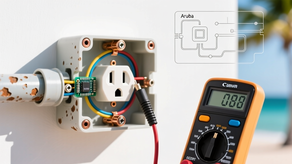
- Secondary Verification: Use a plug-in circuit analyzer (like the Sperry STK-3000) or a multimeter set to AC Voltage (V~). Probe from the hot (short slot) to neutral (long slot), and hot to ground (round hole). Both readings must be exactly 0.0V.
Extraction: Removing the Faulty Receptacle
Once zero-energy state is verified, remove the center faceplate screw using a #2 Phillips or flathead screwdriver. Remove the top and bottom mounting screws securing the yoke to the electrical box. Gently pull the device out of the gang box, being careful not to stress the wires. Inspect the exposed copper and insulation. If the wire insulation is brittle, cracked, or melted back more than 1 inch, you must cut the damaged wire back and strip a fresh end, or use a wire nut to pigtail a new length of 14 AWG (or 12 AWG, matching the circuit) THHN copper.
Termination Matrix: Why the 'Backstab' Connection Fails
When wiring your new outlet, you will typically encounter three termination options. Understanding the mechanical differences is crucial for a lasting repair.
| Termination Method | Mechanism | Reliability & Code Status | Recommendation |
|---|---|---|---|
| Push-In (Backstab) | Spring-loaded steel clamp grips 14 AWG solid wire. | Poor. Prone to thermal cycling failure. High resistance over time. Banned for 12 AWG wire. | NEVER USE. Cut off backstabbed wires and re-terminate. |
| Side-Wire (Screw) | Wire wrapped clockwise around a brass screw and torqued down. | Good. Standard for residential. Requires proper stripping and hook formation. | ACCEPTABLE. Use for standard 15A Leviton receptacles. |
| Back-Wire (Clamp) | Wire inserted into a rear hole; screw tightens a solid brass pressure plate. | Excellent. Maximum surface contact. No hook required. Resists pull-out. | BEST PRACTICE. Use on commercial-grade (Eaton/Hubbell) outlets. |
Wiring the Upgrade: Step-by-Step Termination
If you are using the side-wire (screw) method on a standard 15A receptacle, precision is key. Follow these exact measurements:
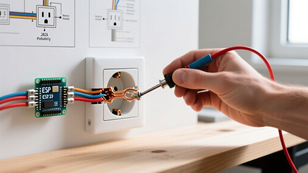
- Strip the Wire: Use the built-in stripping gauge on the back of the receptacle. Typically, you need exactly 3/4 inch of bare copper. Do not score or nick the wire, as this creates a shear point that can snap under torque.
- Form the Shepherd's Hook: Using long-nose pliers, bend the bare copper into a tight, 180-degree hook. The hook must be perfectly rounded, not kinked.
- Clockwise Placement: Loop the wire around the terminal screw in a clockwise direction. This ensures that as you tighten the screw to the right, the loop closes tightly around the shaft rather than being pushed outward.
- Torque and Inspect: Tighten the screw until the brass plate clamps down firmly on the wire insulation. There should be no bare copper visible outside the terminal, and no loose insulation trapped under the screw head.
- Grounding: Connect the bare copper or green ground wire to the green grounding screw at the bottom of the yoke. If the box is metal, you must also run a ground pigtail from the box to the receptacle to ensure a continuous grounding path.
2026 NEC Code Requirements for Replacements
The National Fire Protection Association (NFPA) updates the National Electrical Code (NEC) every three years. When replacing a broken electrical outlet, your new installation must comply with current local adoptions of the NEC.
Tamper-Resistant (TR) Mandate
Per NEC Article 406.12, all 15A and 20A, 125V and 250V non-locking receptacles installed in dwelling units must be listed as Tamper-Resistant. TR receptacles feature internal spring-loaded shutters that only open when equal pressure is applied to both slots simultaneously (like a standard plug). If you are replacing an old, broken outlet in a home built before 2008, you must upgrade to a TR model, even if it is a simple like-for-like swap.
GFCI and AFCI Edge Cases
If the broken outlet is located in a kitchen, bathroom, garage, outdoors, or within 6 feet of a wet bar sink, NEC Article 210.8 requires Ground-Fault Circuit Interrupter (GFCI) protection. If the existing wiring lacks an equipment grounding conductor (common in pre-1960s homes), the U.S. Department of Energy and the NEC permit replacing the broken ungrounded outlet with a GFCI receptacle. You must connect the hot and neutral wires, leave the ground screw empty, and apply the provided 'GFCI Protected - No Equipment Ground' sticker to the faceplate. This provides life-saving shock protection without the massive expense of rewiring the entire house.
Cost Analysis: DIY Replacement vs. Hiring an Electrician
Understanding the financial landscape helps you decide whether to tackle the repair yourself or call a licensed professional. Below are average 2026 market rates for a single-outlet replacement.
| Service Level | Material Cost | Labor / Trip Charge | Total Estimated Cost | Time Required |
|---|---|---|---|---|
| DIY (Standard 15A TR) | $3.50 - $6.00 | $0.00 | $3.50 - $6.00 | 20 - 30 Minutes |
| DIY (20A Commercial) | $12.00 - $18.00 | $0.00 | $12.00 - $18.00 | 25 - 40 Minutes |
| Licensed Electrician | $5.00 - $15.00 | $125.00 - $250.00 | $130.00 - $265.00 | 1 Hour (Minimum Trip) |
Note: Electrician trip charges vary wildly by metropolitan area. If you only have one broken outlet, the DIY route is highly cost-effective, provided you have the correct safety tools. If you have multiple failing outlets, an electrician's hourly rate becomes more economical.
Frequently Asked Questions
Can I replace a 15-amp outlet with a 20-amp outlet?
Only if the circuit wiring is 12 AWG copper and the breaker is rated for 20 amps. If your home is wired with 14 AWG copper (standard for 15-amp circuits), installing a 20-amp receptacle is a severe code violation and fire hazard, as the wire will overheat before the breaker trips. Always match the receptacle amperage to the wire gauge and breaker size.
Why are there two sets of wires (4 cables) connected to my old outlet?
This indicates the outlet is in the middle of a 'daisy chain' circuit. One set of wires brings power (Line) from the breaker panel, and the second set carries power (Load) downstream to the next outlet. You must connect both sets to the new receptacle: both black (hot) wires to the brass screws, both white (neutral) wires to the silver screws, and all bare ground wires pigtailed together and attached to the green screw.
My new outlet has a breaking fin on the side. Should I snap it off?
Leave the metal tabs intact unless you are intentionally splitting the receptacle (e.g., in a kitchen where the top half is controlled by a wall switch and the bottom half is always hot, or in a multi-wire branch circuit setup). For a standard replacement of a broken electrical outlet, the tabs must remain connected to ensure power flows through the device to downstream outlets.