
The Anatomy of a 'Broken' Electrical Outlet
When a homeowner reports an electrical outlet broken, the root cause is rarely a simple manufacturing defect. In 90% of residential cases, the failure stems from thermal fatigue, improper backstab wiring, or misconfigured split-receptacle tabs. Understanding the internal wiring diagram of a standard 15A or 20A duplex receptacle is critical for accurate diagnosis and safe replacement.
According to the Electrical Safety Foundation International (ESFI), aging and improperly wired receptacles are a leading cause of residential electrical fires. This wiring diagram reference guide will help you isolate the exact failure node, interpret multimeter readings, and execute a code-compliant repair.
Diagnostic Matrix: Why Is Your Electrical Outlet Broken?
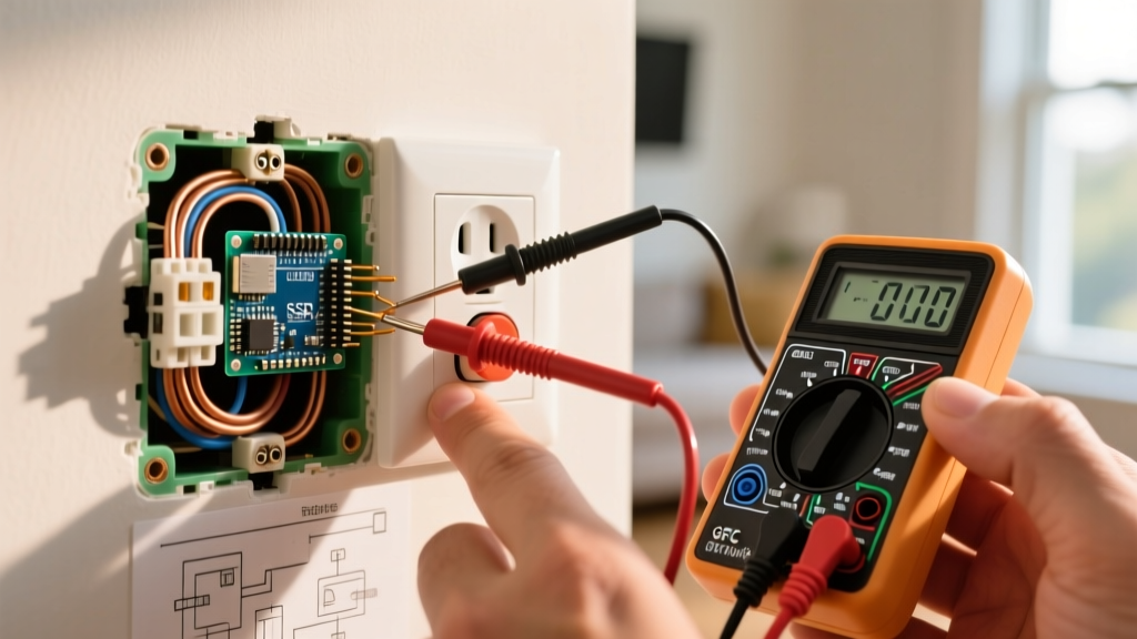
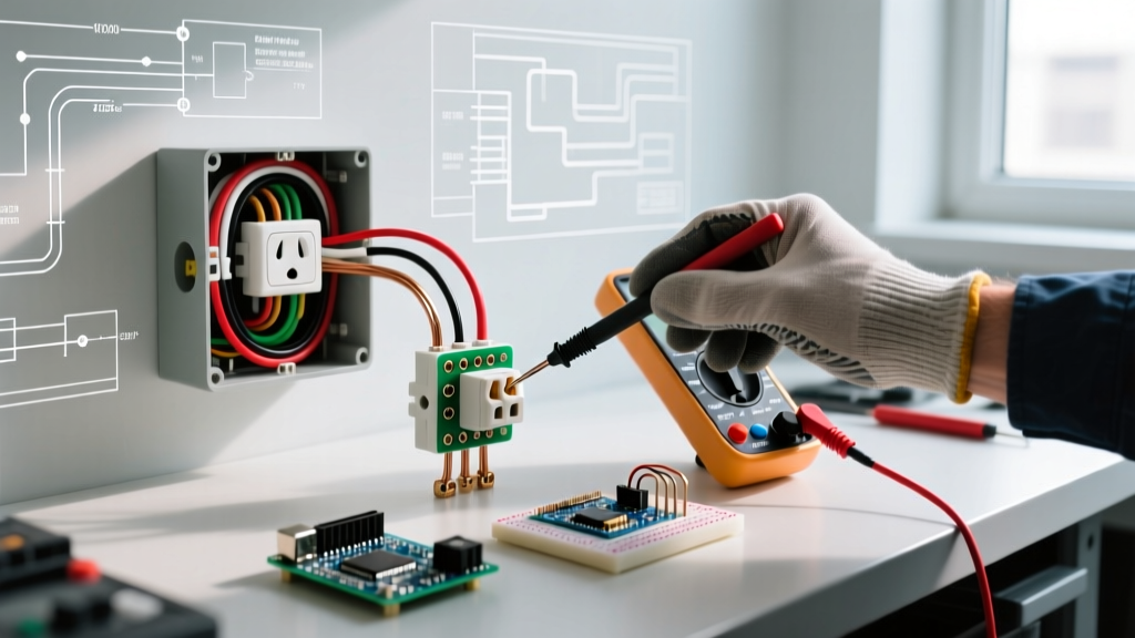
Before removing the faceplate, use a non-contact voltage tester and a digital multimeter to categorize the failure. Reference the matrix below to match your symptoms to the underlying wiring fault.
| Failure Mode | Visual Symptom | Multimeter Reading (Hot to Neutral) | Wiring Diagram Fix |
|---|---|---|---|
| Backstab Thermal Failure | Melted rear housing; discolored slots | Intermittent 0V - 120V | Cut back wire, strip 5/8', use side-terminal J-hook. |
| Severed Brass Tab (Split) | Top half dead, bottom half live | 0V Top / 120V Bottom | Replace with new split-receptacle; break brass fin. |
| GFCI Load Miswire | Downstream outlets dead; won't reset | 120V at Line / 0V at Load | Route incoming power to LINE, downstream to LOAD. |
| Reversed Polarity | No visual signs; tester shows hot/neutral swap | 120V on Neutral-Ground | Swap black (brass) and white (silver) wire positions. |
Wiring Diagram Reference: Standard vs. Split-Receptacle
Standard 15A/20A Duplex (e.g., Leviton T52-R)
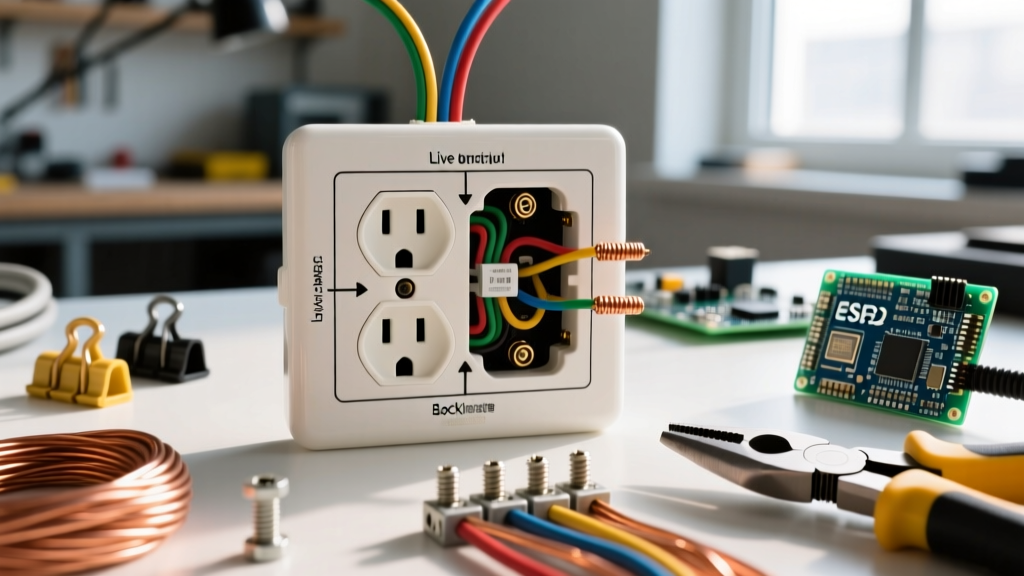
A standard duplex receptacle features two brass (hot) terminals, two silver (neutral) terminals, and one green (ground) terminal. Internally, metal fins connect the top and bottom brass screws, and another fin connects the silver screws. If your electrical outlet broken diagnosis points to a standard failure, you are likely dealing with a loose neutral or a degraded hot connection on the side terminals.
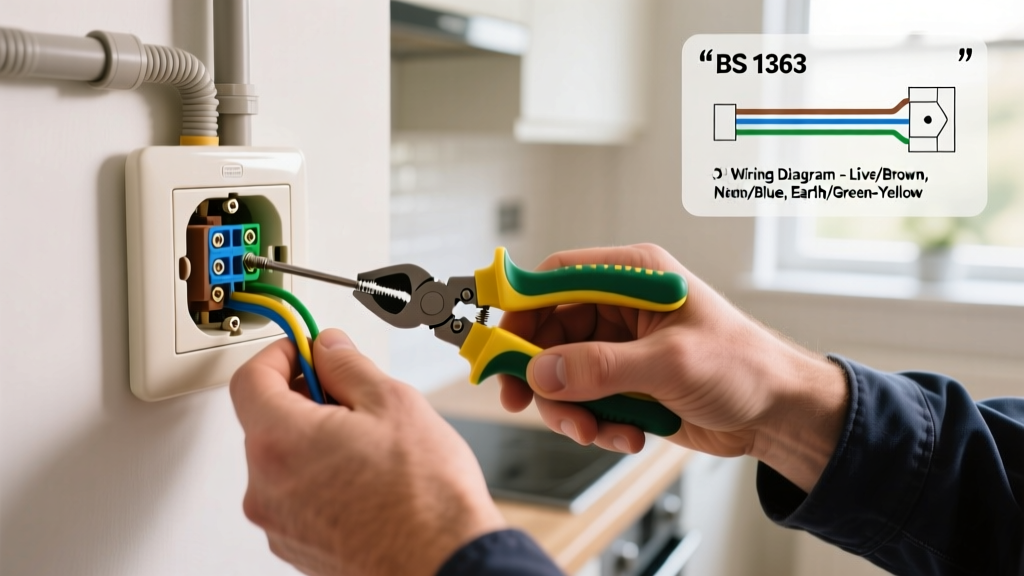
- Black (Hot) Wire: Connects to the brass screw. The J-hook must face clockwise so tightening the screw pulls the loop closed.
- White (Neutral) Wire: Connects to the silver screw. Never place neutral on a brass terminal, as this creates a severe shock hazard.
- Bare/Green (Ground): Connects to the green hexagonal screw at the base.
Split-Wired (Half-Hot) Receptacle Diagram
In living rooms and dining areas, it is common to have a split-wired receptacle where a wall switch controls the top half, while the bottom half remains constantly hot for lamps or vacuums. If you are replacing an electrical outlet broken in this configuration, the wiring diagram requires a crucial physical modification.
You must use needle-nose pliers to snap off the small metal breakaway fin connecting the two brass (hot) terminals. If you forget this step, feeding 120V from the panel to the bottom and 120V from the switch to the top will result in a dead short, tripping the breaker immediately.
Backstab vs. Side-Wire: The Thermal Fatigue Factor
Many older homes feature receptacles wired using push-in backstab connections. While the NEC permits backstabbing for 14 AWG solid wire, it is universally condemned by professional electricians as a primary cause of an electrical outlet broken down over time. The internal spring-loaded brass wedges grip the wire with minimal surface area. As the circuit experiences load—such as a 1300W microwave drawing 11 amps—the wire heats up and expands. When the load stops, it cools and contracts. Over hundreds of thermal cycles, this microscopic movement loosens the grip, increasing resistance. Higher resistance leads to more heat, eventually melting the polycarbonate housing and causing an open circuit or arc fault.
The Fix: Never use backstab connections on replacement outlets. Always use the side-terminal screws. If the wire is too short or damaged from previous backstab removal, cut it back, re-strip to 5/8', and form a fresh J-hook. If you are dealing with stranded wire or 12 AWG wire (which cannot be backstabbed legally on most 15A devices), side-wiring or using a pigtail wire nut connection is your only code-compliant option.
GFCI Line vs. Load Wiring Errors
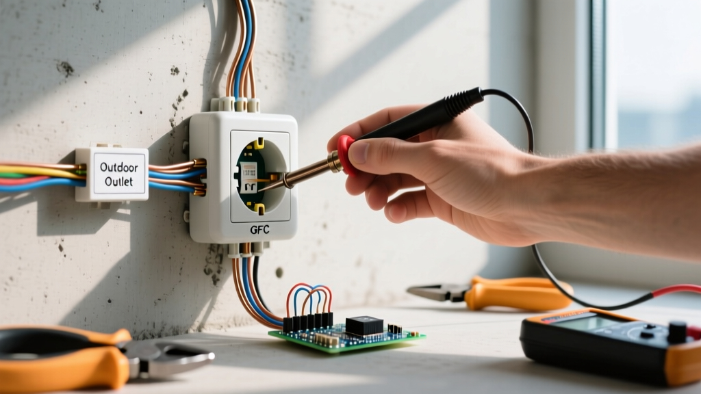
A frequent reason users believe their GFCI electrical outlet broken is due to a fundamental misunderstanding of the LINE and LOAD terminals. The NFPA 70 National Electrical Code (NEC) mandates GFCI protection in wet areas, but miswiring defeats the purpose.
- LINE Terminals: These receive the incoming power directly from the circuit breaker panel. If power is wired here, the GFCI will function and protect itself.
- LOAD Terminals: These feed power to downstream standard receptacles, extending GFCI protection to them. If you accidentally wire the incoming panel power to the LOAD terminals, the GFCI may trip instantly, refuse to reset, or fail to protect downstream devices, leading to the false assumption that the unit is defective.
Step-by-Step Replacement & Torque Specifications
When replacing a faulty receptacle, precision matters. The U.S. Consumer Product Safety Commission (CPSC) emphasizes that loose connections cause arcing and fires. Follow these exact specifications for a commercial-grade replacement like the Hubbell 5262:
- Kill the Power: Turn off the breaker and verify 0V using a Fluke 117 multimeter between hot and neutral, and hot and ground.
- Strip to the Gauge: Use a Klein Tools 11055 wire stripper. Match the wire insulation to the 5/8-inch (16mm) strip gauge molded into the back of the receptacle. Exposed copper beyond the terminal screw is a shock hazard.
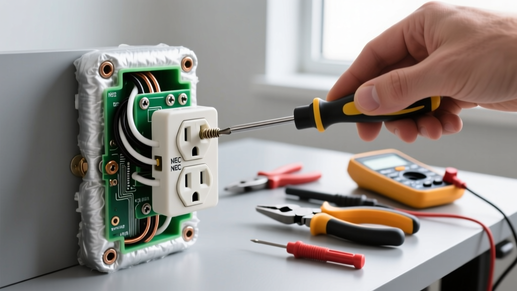
- Form the J-Hook: Use needle-nose pliers to bend the stripped solid copper wire into a tight hook. Ensure the hook is oriented clockwise.
- Torque the Screws: Tighten the terminal screws firmly. While many residential electricians rely on 'feel', modern commercial specs recommend approximately 14 in-lbs of torque to prevent thermal creep over years of heating and cooling cycles.
- Wrap with Electrical Tape: Wrap two layers of 3M Super 33+ vinyl tape around the sides of the receptacle to cover the exposed terminal screws before pushing it into the metal or plastic gang box.
Frequently Asked Questions
Why does my outlet spark when I plug something in?
A small blue spark is normal inductive arcing when plugging in high-draw appliances like vacuums. However, a large orange spark accompanied by a burning smell indicates a loose internal connection or degraded backstab wiring. Treat this as an electrical outlet broken scenario and replace it immediately using side-wiring.
Do I need a Tamper-Resistant (TR) receptacle?
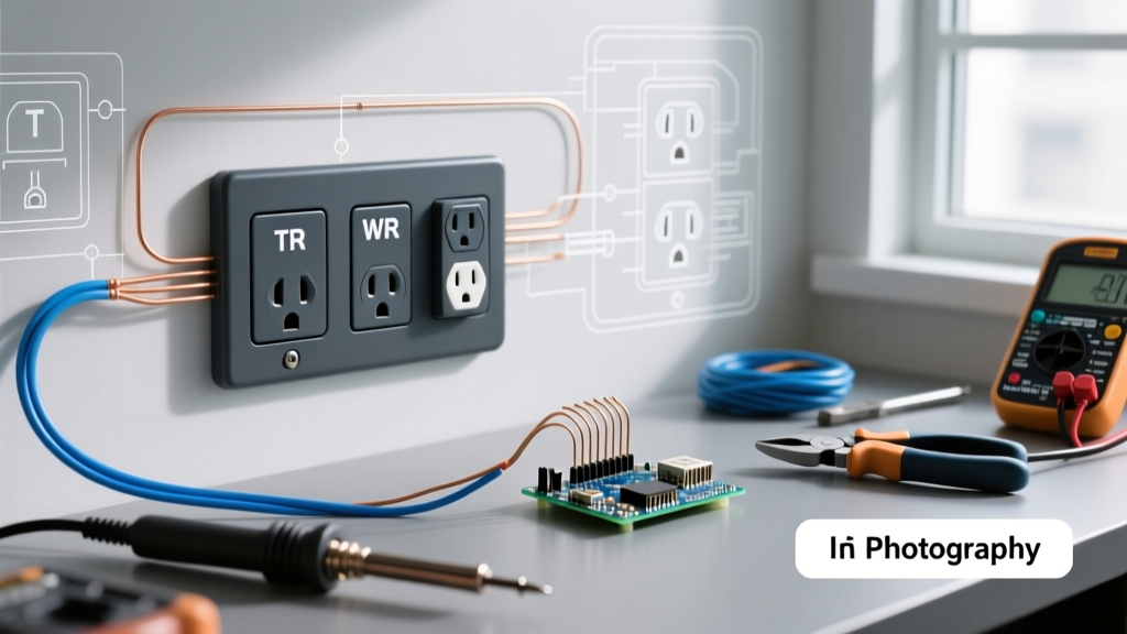
Yes. Under NEC Article 406.12, all 15A and 20A receptacles in dwelling units must be Tamper-Resistant. TR receptacles feature internal spring-loaded shutters that only open when equal pressure is applied to both slots simultaneously, preventing children from inserting foreign objects. Always buy TR-rated models for residential replacements.