
The Critical Role of Schematic Symbols in Electrical Diagnosis
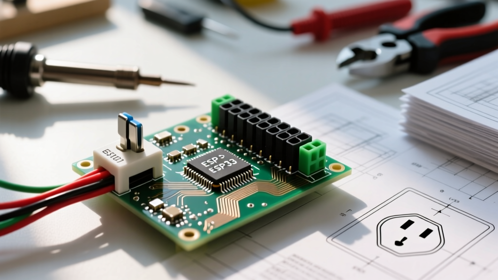
When a complex branch circuit fails, jumping straight to the physical receptacle with a multimeter is a rookie mistake. Professional electrical troubleshooting begins at the drafting table. The architectural and electrical blueprints hold the roadmap of the circuit's intended design. Misinterpreting the symbol for electric outlet on these schematics is one of the most common reasons electricians and advanced DIYers go down the wrong diagnostic path, leading to wasted hours, unnecessary component replacements, and potentially dangerous miswiring.
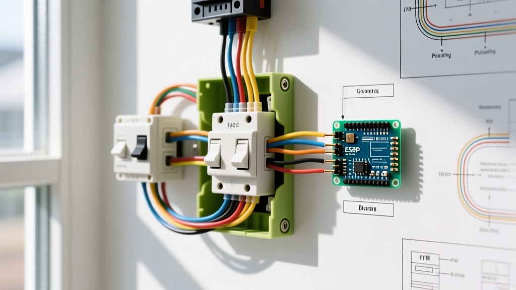
In 2026, with the widespread adoption of smart home integration, Dual-Function (DF) AFCI/GFCI receptacles, and strict energy code requirements, the standard duplex receptacle is no longer the only device on the wall. Understanding the nuanced variations of outlet symbols is mandatory for accurate fault isolation. This guide bridges the gap between blueprint reading and physical circuit diagnosis, providing actionable workflows to trace schematic symbols to real-world wiring faults.
Standard vs. Specialty: Decoding Outlet Symbols
Electrical blueprints utilize standardized symbols governed by organizations like the IEEE and ANSI. However, architectural plans often use shorthand variations. Below is a diagnostic matrix correlating common blueprint symbols to their physical counterparts and the specific troubleshooting pitfalls associated with each.
| Blueprint Symbol Description | Physical Receptacle Type | Common Diagnostic Pitfalls |
|---|---|---|
| Two parallel semicircles on a vertical line | Standard 15A/125V Duplex (NEMA 5-15R) | Assuming both halves are always hot; failing to check for hidden switch loops. |
| Standard symbol with one half shaded black | Half-Switched (Split-Wired) Duplex | Replacing without breaking the hot-side fin tab; diagnosing the 'dead' half as a wiring fault. |
| Standard symbol with 'GFCI' or 'CI' text | Ground Fault Circuit Interrupter | Troubleshooting downstream standard outlets without checking the upstream GFCI 'LOAD' terminals. |
| Standard symbol with an internal triangle | Isolated Ground (IG) - Orange Receptacle | Using the subpanel ground bar for continuity testing instead of tracing the dedicated IG wire to the main panel. |
| Large circle with '14-50R' or 'L14-30R' | 240V High-Voltage Receptacle (Dryer/Range/EV) | Testing line-to-neutral expecting 120V; misdiagnosing a missing neutral on a pure 240V NEMA 6-50R. |
Real-World Troubleshooting Scenarios: When Symbols Mislead
To demonstrate the importance of schematic literacy, let us examine three common field scenarios where ignoring or misreading the symbol for electric outlet results in a failed diagnosis.
Scenario 1: The Half-Switched 'Dead' Outlet
The Complaint: A homeowner reports the bottom half of a living room outlet is completely dead, while the top half works.
The Misdiagnosis: The technician assumes a broken wire nut in the junction box or a failed backstab connection. They pull the receptacle, find the wiring intact, and replace it with a new $3 Leviton 15A duplex. The bottom half remains dead.
The Schematic Truth: The blueprint showed the outlet symbol with the bottom half shaded. This indicates a split-wired receptacle controlled by a wall switch. The technician failed to break off the brass (hot-side) connecting fin on the new receptacle.
The Fix: Use needle-nose pliers to twist and snap the brass fin tab between the two brass screws. This isolates the top and bottom terminals, allowing the wall switch to control the bottom half while the top remains constantly hot via the always-hot black wire.
Scenario 2: The Isolated Ground (IG) Ghost Voltage
The Complaint: Sensitive audio equipment in a studio is experiencing a 60Hz hum. The blueprint symbol for electric outlet in this room features the distinct internal triangle, denoting an Isolated Ground (IG) receptacle (typically orange in color).
The Misdiagnosis: Using a standard Fluke 117 True-RMS multimeter, the tech measures Neutral-to-Ground voltage at the receptacle and reads 1.5V, assuming a loose neutral on the branch circuit.
The Schematic Truth: Per NEC Article 250.146(D), an IG receptacle's green grounding terminal is insulated from the metal yoke. The grounding path travels via a dedicated equipment grounding conductor (EGC) directly back to the main service panel, completely bypassing the subpanel's ground bus to prevent ground loops.
The Fix: Stop testing continuity to the local subpanel ground bar. Trace the dedicated orange or green EGC wire back to the main panel. The 1.5V reading is likely induced phantom voltage; switch the multimeter to a low-impedance (LoZ) mode to bleed off the ghost voltage and verify the true ground path.
Scenario 3: Downstream GFCI Protection Confusion
The Complaint: A standard duplex outlet in a bathroom vanity is dead. The breaker in the panel is ON and reads 120V at the bus bar.
The Misdiagnosis: The troubleshooter tears open the dead standard outlet, checks the pigtails, and finds no voltage. They begin fishing walls to find a broken wire.
The Schematic Truth: The blueprint shows a GFCI symbol near the bathroom door, with a dashed line connecting to the standard outlet symbol at the vanity. This dashed line indicates the standard outlet is wired to the LOAD terminals of the upstream GFCI.
The Fix: Locate the upstream GFCI device. Press the 'TEST' and 'RESET' buttons. In 90% of these cases, a nuisance trip on the upstream GFCI has cut power to the downstream LOAD circuit. Always consult the schematic to map out GFCI protected zones before tearing into drywall.
Expert Diagnostic Tip: Never rely solely on a $15 Gardner Bender GRT-9300 receptacle tester for GFCI diagnosis. While useful for checking basic wiring (open neutral, reversed polarity), these testers inject a fault current that can sometimes fail to trip older or degraded GFCI internal solenoids. Always use the physical 'TEST' button on the receptacle face, which utilizes the device's internal circuitry to verify true mechanical and electrical functionality.
Step-by-Step Blueprint-to-Multimeter Diagnostic Workflow
When approaching a complex circuit failure, follow this systematic workflow to translate the symbol for electric outlet into actionable multimeter tests.
- Identify the Circuit Topology: Locate the outlet symbol on the electrical plan. Note the circuit number (e.g., 'Ckt 4') and trace it back to the panel schedule to determine the breaker size (15A vs 20A) and wire gauge (14 AWG vs 12 AWG).
- Verify Receptacle Rating: If the blueprint calls for a 20A symbol (often denoted by a 'T' shaped neutral slot note or '20A' text), ensure the physical receptacle is a NEMA 5-20R. Installing a 15A receptacle on a 20A breaker is a direct violation of NEC 2026 code and a major fire hazard.
- Perform the 3-Point Voltage Test: Using a CAT III rated multimeter (like the Klein Tools MM700), measure:
- Line to Neutral: Should read 120V (±5%).
- Line to Ground: Should read 120V (±5%).
- Neutral to Ground: Should read < 2V. If it reads >2V, you have a voltage drop on the neutral wire, indicating a loose connection or an overloaded shared neutral (Multi-Wire Branch Circuit fault).
- Check for Bootleg Grounds: If Line-to-Ground reads 120V, but the receptacle tester shows an 'Open Ground', the previous installer may have wired a jumper between the neutral and ground screws to cheat the inspection. This is lethal. Disconnect power and verify physical wire terminations.
NEC Code Updates and Schematic Evolution
The National Fire Protection Association (NFPA) continuously updates the National Electrical Code (NEC) to improve safety. Recent code cycles have drastically expanded AFCI and GFCI requirements. In modern blueprints, you will increasingly see symbols for Dual-Function (DF) receptacles, which combine both Arc Fault and Ground Fault protection in a single device.
Furthermore, the Occupational Safety and Health Administration (OSHA) mandates strict adherence to lockout/tagout (LOTO) procedures during diagnostic testing. When tracing a circuit from a blueprint symbol to the physical panel, always verify the absence of voltage with a properly rated non-contact voltage tester (like the Fluke 1AC-II VoltAlert) before removing any receptacle cover plates. Remember that Multi-Wire Branch Circuits (MWBC) require simultaneous disconnection of all ungrounded conductors; a single breaker toggle may not de-energize the entire outlet if it is fed by a shared neutral setup.
Frequently Asked Questions (FAQ)
What does a circle with a 'W' mean next to the outlet symbol?
A 'W' next to an outlet symbol typically denotes a weather-resistant (WR) receptacle. These are required for outdoor damp and wet locations per NEC Article 406.9. When troubleshooting outdoor circuits, ensure the physical receptacle has the 'WR' stamp on the yoke and is paired with an extra-duty while-in-use bubble cover.
How do I identify a 240V EV charger outlet on a blueprint?
Electric Vehicle Supply Equipment (EVSE) outlets are usually denoted by a large circle with specific NEMA text, most commonly 'NEMA 14-50R' (50A, 125/250V). Troubleshooting these requires a CAT IV multimeter and an understanding of split-phase power. You must measure 240V between the two hot lines (X and Y), and 120V from either hot line to the neutral.
Why does the blueprint show a standard symbol, but the physical outlet has a red reset button?
Architectural blueprints are sometimes not updated with final field changes or 'as-built' redlines. If the physical outlet is an AFCI or GFCI but the blueprint shows a standard symbol, trust the physical device. The circuit is likely protected locally rather than at the breaker panel, which changes your entire downstream diagnostic strategy.