
Beyond the Basics: Code-Compliant Receptacle Wiring
When you look at a standard wiring diagram for wall outlet configurations, it appears deceptively simple: black to brass, white to silver, and bare copper to green. However, passing a rough-in and final electrical inspection requires far more than basic continuity. The National Electrical Code (NEC) enforces strict parameters regarding box fill, torque specifications, device continuity, and arc-fault protection that transform a basic DIY sketch into a legally compliant, fire-safe installation.
As of the 2023 and widely adopted 2026 NEC cycles, inspectors are cracking down on outdated practices like backstabbing and improper neutral pigtailing. This guide breaks down the exact code requirements you must follow when executing your wiring diagram for wall outlet projects, ensuring your 15A and 20A 120V receptacle installations are safe, durable, and fully compliant.
The Physical Wiring Diagram for Wall Outlet Terminals
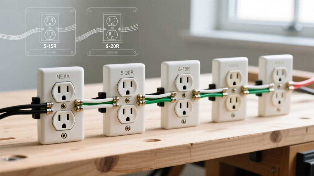
The physical wiring diagram for wall outlet terminals dictates that the ungrounded (hot) conductor connects to the brass screw, the grounded (neutral) conductor connects to the silver screw, and the equipment grounding conductor connects to the green screw. While this color-coding is universal, the method of termination is heavily regulated.
Code Callout: NEC 110.3(B) - Installation and Use
Listed equipment must be installed in accordance with the instructions included in the listing. Most modern commercial-grade receptacles (like the Leviton 5362 or Hubbell 5262) explicitly prohibit the use of "push-in" backstab terminals for 12 AWG wire and strongly advise against them for 14 AWG wire due to historical failure rates and thermal expansion issues.
Proper Side-Wiring Technique
For a code-compliant side-wired connection, you must utilize the built-in wire strip gauge located on the back of the receptacle yoke.
- 14 AWG Solid Copper: Requires exactly 5/8-inch of stripped insulation.
- 12 AWG Solid Copper: Requires exactly 3/4-inch of stripped insulation.
The wire must be looped clockwise around the terminal screw. This ensures that as the screw is tightened, the loop pulls tighter around the screw shaft rather than being pushed outward. The insulation should sit flush against the washer of the terminal screw—no exposed copper should be visible outside the terminal plate, which prevents accidental shorting against the metal device box.
NEC 406.12 & 210.8: Tamper-Resistant and GFCI Mandates
Your wiring diagram is irrelevant if the device itself violates modern listing requirements. The NEC has drastically updated where specific receptacle types must be used.
Tamper-Resistant (TR) Receptacles
Under NEC 406.12, all 15A and 20A, 125V and 250V non-locking receptacles installed in dwelling units, guest rooms, and childcare facilities must be Tamper-Resistant (TR). TR receptacles feature internal shutter mechanisms that only open when equal, simultaneous pressure is applied to both slots (like a standard plug). Attempting to insert a single object, like a paperclip or a child's finger, will not depress the shutters. There are no exceptions for outlets located behind heavy furniture or above countertops.
GFCI and AFCI Protection
While the physical wiring diagram for the outlet remains the same, the circuit feeding it must comply with NEC 210.8 (GFCI) and 210.12 (AFCI).
- GFCI: Required in all wet or damp locations (kitchens, bathrooms, garages, outdoors, crawlspaces, and within 6 feet of any sink). You can achieve this via a GFCI receptacle at the first point of the circuit or a GFCI circuit breaker.
- AFCI: Combination-Type Arc-Fault Circuit Interrupters are required for almost all 120V, single-phase, 15A and 20A branch circuits supplying outlets in dwelling unit living spaces, bedrooms, and hallways.
Box Fill Calculations (NEC 314.16)
One of the most common reasons an inspector will fail a wall outlet installation is box fill violation. You cannot simply cram wires and devices into a standard single-gang box. NEC 314.16(B) assigns "volume allowances" to every component inside the box based on the largest wire gauge present.
Volume Allowance Table per Conductor
| Wire Gauge (AWG) | Volume Allowance per Conductor |
|---|---|
| 14 AWG | 2.0 cubic inches |
| 12 AWG | 2.25 cubic inches |
| 10 AWG | 2.5 cubic inches |
Real-World Calculation Example
Imagine you are wiring a 20A kitchen outlet using 12 AWG NM-B cable (which contains a black, white, and bare ground). You are feeding power in and feeding power out to the next receptacle.
- Hot Wires: 2 black wires = 2 allowances
- Neutral Wires: 2 white wires = 2 allowances
- Ground Wires: All bare grounds combined = 1 allowance
- Internal Clamps: If present = 1 allowance (0 for old-work drywall boxes)
- The Device (Receptacle): Counts as 2 allowances based on the largest wire connected to it.
Total Allowances: 2 + 2 + 1 + 0 + 2 = 7 allowances.
Since you are using 12 AWG wire, multiply 7 by 2.25 cubic inches.
Total Required Box Volume: 15.75 cubic inches.
Critical Insight: A standard 14-cubic-inch single-gang old-work box is illegal for this setup. You must use a "deep" single-gang box rated for at least 16 cubic inches (commonly 18 or 20 cu in boxes are used by professionals to ensure compliance and ease of folding).
Torque Requirements: The Hidden Code (NEC 110.14)
Historically, electricians tightened terminal screws until they "felt tight." The modern NEC, specifically 110.14(D), mandates that terminations must be tightened to the torque values specified by the manufacturer using a calibrated torque screwdriver.
For standard commercial-grade 15A and 20A duplex receptacles, the manufacturer typically specifies a torque range of 12 to 14 inch-pounds for 14 and 12 AWG solid copper wire. Under-torquing leads to thermal expansion and contraction cycles that loosen the connection over time, creating high-resistance arcing. Over-torquing can strip the brass screw threads or shear the wire, reducing the cross-sectional area and creating a bottleneck for current flow.
Multiwire Branch Circuits (MWBC) and Neutral Pigtailing
If your wiring diagram for the wall outlet involves a Multiwire Branch Circuit (two hot wires sharing a single neutral), you must adhere strictly to NEC 300.13(B).
You cannot use the receptacle's internal metal yoke or the side terminal screws to daisy-chain the neutral wire to the next outlet. The neutral must be spliced together in the back of the box using a wire nut or WAGO connector, and a single "pigtail" must be run to the receptacle's silver screw.
The Danger of Breaking the Neutral:
If you daisy-chain the neutral through the receptacle and later remove that receptacle for replacement while the circuit is still live, you break the neutral return path for the downstream half of the MWBC. This forces the two 120V legs into a series circuit, sending 240V through downstream 120V appliances, instantly destroying electronics and creating a severe fire hazard.
Step-by-Step Code-Compliant Execution Flow
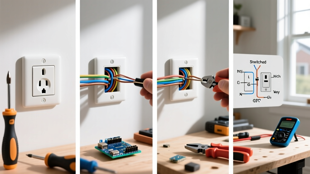
- Verify Power: Use a non-contact voltage tester and a plug-in circuit analyzer to confirm the circuit is de-energized.
- Calculate Box Fill: Ensure the existing or new electrical box meets the cubic inch requirements for the wire gauge and number of conductors.
- Strip to the Gauge: Use the physical strip gauge on the back of the receptacle yoke. Do not nick the copper conductor with your wire strippers, as nicks create weak points that snap under torque.
- Pigtail if Necessary: Use 12 AWG pigtails for 12 AWG circuits, and 14 AWG for 14 AWG circuits. Never mix gauges in a way that violates the overcurrent protection device rating.
- Form the Loop: Create a tight, clockwise hook. Ensure no bare copper extends beyond the terminal washer.
- Torque the Screws: Set a calibrated torque screwdriver to 12 in-lbs (or the manufacturer's exact spec) and tighten the brass, silver, and green screws.
- Fold, Don't Cram: Carefully fold the grounding wires into the back corners of the box, followed by the neutrals, and finally the hot wires. Push the receptacle in evenly to avoid cracking the drywall or bending the yoke.
Frequently Asked Questions (FAQ)
Can I use 14 AWG wire on a 20A circuit?
No. NEC 240.4(D) strictly limits 14 AWG copper to a maximum 15A overcurrent protection device. If you are wiring a 20A outlet (identified by the T-shaped neutral slot), you must use a minimum of 12 AWG copper wire.
Do I need to wrap electrical tape around the terminal screws?
While not explicitly banned by the NEC, wrapping black electrical tape around the sides of a receptacle to cover the terminal screws is considered an outdated practice by modern inspectors and educators. If the box is properly grounded and the box fill is correct, exposed terminals pose no shock hazard. Furthermore, tape traps heat and can melt or leave a messy residue over decades of thermal cycling.
What is the required height for a standard wall outlet?
The NEC does not specify a standard mounting height for general-purpose wall outlets in dwelling units. The common industry standard of 12 to 16 inches from the finished floor to the center of the box is driven by the Americans with Disabilities Act (ADA) guidelines for commercial spaces and general ergonomic convenience, not the NEC. However, specific appliances (like sump pumps or garage door openers) may have manufacturer-mandated height requirements.