
The Critical Pre-Repair Diagnostic Protocol
Jumping straight into an electric outlet repair without a systematic diagnostic phase is a recipe for misdiagnosed faults, wasted time, and potential safety hazards. According to the U.S. Consumer Product Safety Commission (CPSC), electrical receptacles are involved in thousands of residential fires annually, often stemming from high-resistance connections or degraded internal contacts that a simple visual check would miss. In 2026, with the proliferation of high-draw smart home hubs and EV charging adapters, standard 15A duplex receptacles are under more thermal stress than ever before.
This inspection and testing guide provides a professional-grade framework for evaluating receptacle health. We will move from non-contact visual triage to high-impedance multimeter testing and active load verification, ensuring your repair addresses the root cause, not just the symptom.
Phase 1: Visual and Thermal Triage (De-Energized)
Before touching any tools to the terminal screws, perform a de-energized visual and thermal inspection. Always verify the circuit is dead using a non-contact voltage tester (NCVT) like the Klein Tools NCVT-3, and follow OSHA electrical safety guidelines regarding lockout/tagout procedures at the breaker panel.
Key Visual Failure Indicators
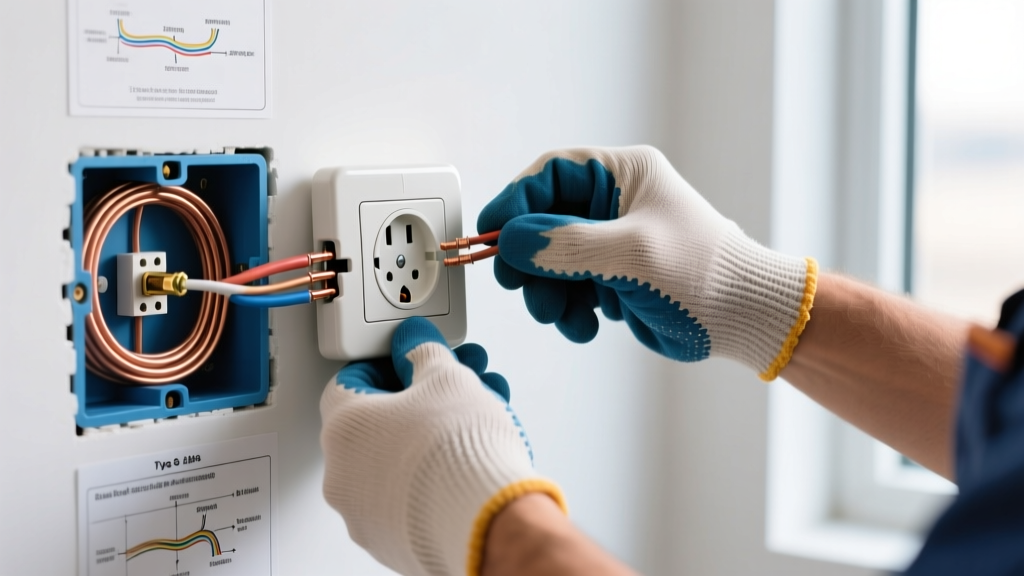
- Backstabbed Push-In Terminals: Builder-grade receptacles (like older Leviton or Pass & Seymour models) often feature push-in wire holes. These rely on a small internal brass spring that loosens over time due to thermal expansion and contraction, leading to arcing. If you see 14 AWG or 12 AWG solid copper wire pushed into the back, plan to migrate them to the side terminal screws or use a pigtail during the repair.
- Thermal Scorching: Brown or black discoloration on the thermoplastic faceplate or the internal brass contacts indicates severe resistive heating. This mandates immediate replacement of the receptacle and inspection of the wire insulation for brittleness.
- Aluminum Wiring Markings: If the outlet is stamped with "CO/ALR" (Copper-Aluminum Revised) or lacks it entirely but you spot silver-colored wire, you are dealing with aluminum branch circuits. Standard copper-rated receptacles will cause galvanic corrosion and eventual fire. You must use CO/ALR rated devices or pigtail with AlumiConn connectors.
Pro-Tip: Thermal Imaging
For high-value diagnostics, use a thermal camera like the FLIR C5 before cutting power. Scan the outlet faceplate while a 1500W load (like a space heater) is running. A temperature delta of more than 15°F (8°C) above ambient room temperature at the slot openings indicates a failing internal wiper contact.
Phase 2: 3-Light Receptacle Tester Diagnostics
Once power is restored, a 3-light receptacle tester (such as the Klein Tools RT210 or Sperry ET6422) provides a rapid, baseline topology check. While it cannot measure exact voltage or detect high-resistance faults, it instantly identifies gross wiring errors.
| Light Pattern (Left-Center-Right) | Condition | Required Repair Action |
|---|---|---|
| Off - Yellow - Yellow | Correct Wiring | No repair needed; proceed to load testing. |
| Off - Yellow - Off | Open Ground | Verify ground wire connection at the box and panel. Check for broken ground pigtails. |
| Off - Off - Yellow | Open Neutral | Critical fault. Check neutral bus bar, upstream daisy-chains, and backstabbed neutrals. |
| Yellow - Yellow - Off | Hot/Neutral Reversed | Swap the black (hot) and white (neutral) wires on the brass and silver screws. |
| Yellow - Off - Yellow | Hot/Ground Reversed | Dangerous. Bootleg ground or miswired panel. Requires immediate professional tracing. |
The GFCI Test Button Nuance
Pressing the black "TEST" button on a standard receptacle tester injects a 4mA to 6mA current leak between the hot and ground conductors. If the outlet is a standard duplex protected by an upstream GFCI, the upstream GFCI should trip. If it does not trip, the upstream GFCI is either defective, lacks a functional ground path to carry the fault current, or is an older pre-2003 model that has exceeded its operational lifespan.
Phase 3: High-Impedance Multimeter Voltage Mapping
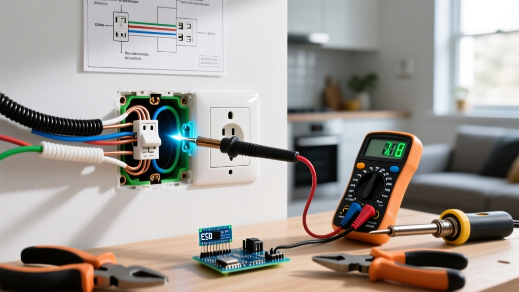
To perform a precise electric outlet repair, you must map the exact voltage relationships using a True-RMS digital multimeter (DMM) with a high input impedance (typically 10 Megohms), such as the Fluke 117 or Klein Tools MM400. This 3-point test confirms the integrity of the entire circuit path.
- Line-to-Neutral (Hot to Neutral): Place the black probe in the neutral (left/longer) slot and the red probe in the hot (right/shorter) slot. You should read between 114V and 126V. A reading below 110V indicates excessive voltage drop, likely from undersized wire on a long run or a loose connection upstream.
- Line-to-Ground (Hot to Ground): Move the black probe to the U-shaped ground hole. The reading should be nearly identical to Line-to-Neutral (within 1V). If it reads significantly lower, you have a high-resistance ground path.
- Neutral-to-Ground: Place the probes in the neutral slot and ground hole. This should read as close to 0.0V as possible. A reading above 2.0V indicates a loaded neutral with high resistance, a shared neutral (multi-wire branch circuit) issue, or a loose neutral bus connection at the main service panel.
Phase 4: Active Load Testing (Catching Phantom Voltage)
The most common point of failure in modern electric outlet repair scenarios is the "phantom voltage" trap. A high-impedance DMM requires almost zero current to take a reading. Therefore, a backstabbed wire that is barely touching the internal spring might read a perfect 120.5V on your Fluke meter. However, the moment you plug in a 12A vacuum cleaner, the high-resistance connection chokes the current, and the voltage at the appliance drops to 45V, causing motor burnout.
How to Perform a Load Test
Use a dedicated plug-in load tester, or simply plug in a known 1500W resistive load (like a hair dryer or space heater). While the load is running, use a clamp meter or a multimeter with a low-impedance (LoZ) setting to measure the voltage. If the voltage drops by more than 5% (below 114V) under a 12.5A load, the receptacle's internal wiper contacts are degraded, or the wire terminations are loose. Replace the receptacle and re-terminate the wires using side-screw connections or lever-nuts (like WAGO 221 series) for pigtailing.
2026 Component Selection and Repair Cost Matrix
When executing the repair, selecting the correct replacement receptacle is paramount for compliance with the National Electrical Code (NEC). All 15A and 20A residential receptacles must now be Tamper-Resistant (TR). Below is a breakdown of common repair scenarios, recommended commercial-spec components, and estimated 2026 costs.
| Repair Scenario | Recommended Component (Commercial Spec) | Part Cost | Est. Labor Cost |
|---|---|---|---|
| Standard 15A Duplex Replacement | Leviton 5262-W (15A TR Duplex, Spec Grade) | $4.50 - $7.00 | $85 - $135 |
| 20A Kitchen/Bathroom Circuit | Hubbell 5262-I (20A TR Duplex, Ivory/White) | $6.00 - $9.50 | $95 - $150 |
| GFCI Protection Upgrade | Leviton GFNL1-W (15A Smart GFCI with Nightlight) | $28.00 - $36.00 | $140 - $210 |
| Aluminum Wire Remediation | AlumiConn 3-Port Connectors + CO/ALR Receptacle | $18.00 - $25.00 | $180 - $275 |
Note: Labor costs assume a licensed electrician billing standard 2026 residential rates ($100-$150/hr) with a minimum one-hour service call charge. DIY repair costs will only reflect the part cost, but require strict adherence to local permitting and NEC guidelines.
Frequently Asked Diagnostic Questions
Why does my outlet read 60V on my multimeter?
A reading of 40V to 70V with no load connected usually indicates "phantom voltage" induced by adjacent live wires in the same cable bundle, combined with an open neutral or open hot connection upstream. Switch your multimeter to the LoZ (Low Impedance) setting. If the voltage drops to 0V, it is phantom voltage, confirming an open circuit that must be traced.
Can I repair a melted outlet by just cleaning the contacts?
Absolutely not. Thermal damage alters the crystalline structure of the brass wiper contacts, destroying their spring tension. Furthermore, the thermoplastic housing becomes brittle and loses its UL-listed dielectric properties. Any outlet showing melt deformation or scorch marks must be completely replaced, and the wire insulation must be stripped back to clean, unburned copper.
How do I test if a GFCI outlet is failing due to age?
GFCI sensors degrade over time, typically lasting 10 to 15 years. If the built-in "TEST" button trips the outlet, but a 3-light tester's GFCI test button (which tests from hot-to-ground) fails to trip it, the GFCI's internal ground-fault sensing coil is likely failing or the equipment grounding conductor is compromised. Replace the GFCI immediately.
Final Safety Verification
After completing your electric outlet repair, re-energize the circuit and repeat the 3-point multimeter test. Verify that the faceplate sits flush against the drywall (using outlet shims if the electrical box is recessed more than 1/4 inch, per NEC 314.20). Finally, torque the terminal screws to the manufacturer's specification—typically 12 to 14 inch-pounds for standard 15A devices—to ensure a lasting, low-resistance connection that will safely handle modern electrical loads for decades to come.