
The Anatomy of a 50-Amp RV Receptacle (NEMA 14-50R)
When planning an electrical upgrade for recreational vehicle charging or campground pedestal installation, understanding the exact wiring diagram for 50 amp RV plug configurations is critical for both safety and equipment longevity. The industry standard for a 50-amp RV connection is the NEMA 14-50R receptacle. Unlike older 3-prong setups that dangerously bonded the neutral and ground, the NEMA 14-50R utilizes a dedicated 4-wire architecture: two hot legs, one neutral, and one equipment grounding conductor.
This configuration provides both 120V (for standard RV appliances) and 240V (for high-draw HVAC systems and EV charging integration) while maintaining a clean, isolated ground path. According to the Recreational Vehicle Industry Association (RVIA), all modern 50-amp RVs are manufactured with 4-prong power cords to match this exact NEMA standard, ensuring the chassis ground remains completely separate from the current-carrying neutral wire.
NEC Code Requirements for 50-Amp RV Circuits
Installing a 50-amp circuit is not merely about connecting wires to terminals; it requires strict adherence to the National Electrical Code (NEC). The National Fire Protection Association (NFPA) outlines specific mandates in Article 210 (Branch Circuits) and Article 551 (Recreational Vehicles) that dictate how these circuits must be protected, routed, and terminated.
The GFCI Mandate and the RV Nuisance Tripping Dilemma
2026 Code Alert: Under recent NEC adoption cycles, outdoor receptacles rated 50 amps or less require Ground-Fault Circuit Interrupter (GFCI) protection. While this is a massive safety upgrade for wet environments, RV owners frequently report nuisance tripping when plugging into residential outdoor 14-50R outlets. This is often caused by the RV's internal Electrical Management System (EMS) or inverter/charger capacitors leaking micro-amps to ground upon initial connection. If your local Authority Having Jurisdiction (AHJ) enforces the outdoor GFCI rule, you must install a 50A GFCI breaker (such as the Siemens Q250GFI or Eaton GFCB250, which typically cost between $180 and $250), rather than a standard $15 double-pole breaker.
Step-by-Step Wiring Diagram & Terminal Mapping
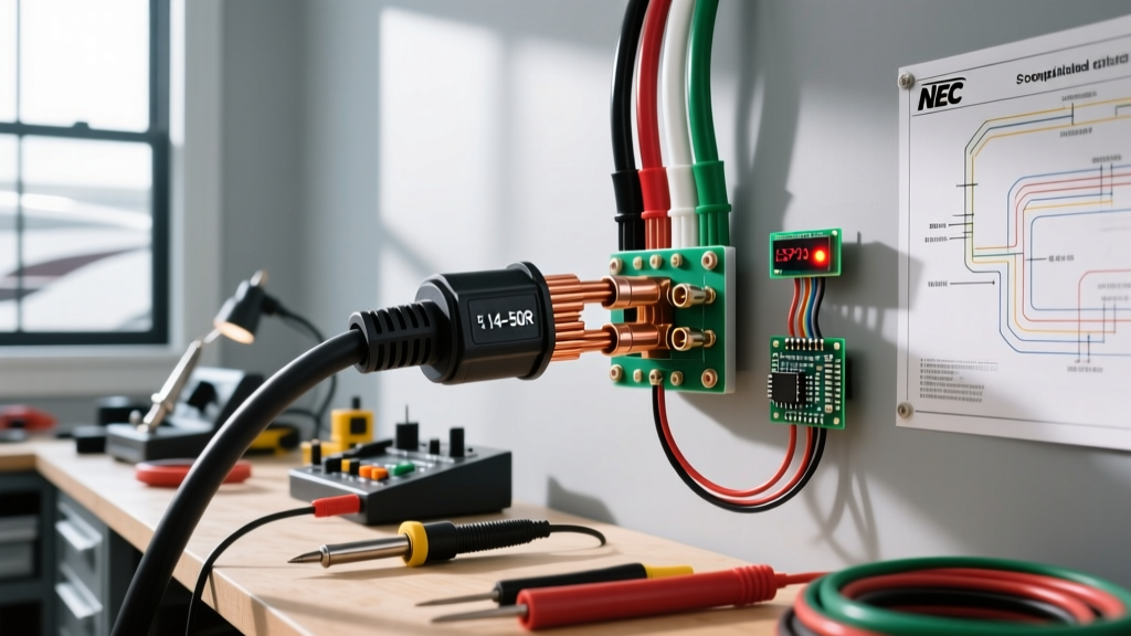
The physical wiring diagram for a 50 amp RV plug relies on precise terminal mapping. The NEMA 14-50R receptacle features four distinct terminals, usually marked on the back of the device body. Reversing the hot and neutral wires or bootlegging the ground are severe code violations that can instantly destroy an RV's sensitive electronics or create a fatal shock hazard.
| Terminal Marking | Wire Color (THHN) | Function | Voltage to Ground |
|---|---|---|---|
| X (Brass Screw) | Black | Hot 1 (Line A) | 120V |
| Y (Brass Screw) | Red | Hot 2 (Line B) | 120V |
| W (Silver Screw) | White | Neutral (Grounded) | 0V |
| G (Green Screw) | Green / Bare | Equipment Ground | 0V |
Note: Always verify terminal markings on your specific receptacle model. For example, the Leviton 279-S00 clearly stamps X, Y, W, and G into the thermoplastic body.
Sizing the Breaker and Wire Gauge (Copper vs. Aluminum)
A 50-amp circuit requires a 50-amp double-pole breaker. However, the conductor sizing depends heavily on the material you choose and the distance from your main service panel to the receptacle. NEC Table 310.16 dictates the baseline ampacities, but voltage drop calculations are essential for RV applications to prevent AC compressor failure.
Copper vs. Aluminum Conductors
- 6 AWG Copper (THHN/THWN): Rated for 55 amps to 75 amps (depending on insulation temperature rating and terminal limitations). This is the standard choice for runs under 50 feet. A 50-foot spool of 6 AWG stranded copper typically costs around $120 to $160 in 2026.
- 4 AWG Aluminum (XHHW-2): Aluminum is significantly cheaper but requires a larger gauge to carry the same current safely. 4 AWG aluminum is rated for 55 amps at 75°C. It is highly recommended for long underground runs in PVC conduit where the cost of copper becomes prohibitive.
The Voltage Drop Factor
The NEC recommends a maximum voltage drop of 3% for branch circuits. If your RV pedestal is located 80 feet from your main panel, 6 AWG copper will experience a voltage drop that could cause your RV's surge protector to trigger a low-voltage fault. For any run exceeding 60 feet, you must upsize to 4 AWG Copper or 2 AWG Aluminum to maintain voltage stability under heavy load.
Torque Specifications: The Hidden Code Violation
One of the most frequently overlooked NEC requirements is Article 110.14(D), which mandates that all electrical terminations be torqued to the manufacturer's specified values using a calibrated torque tool. Guessing the tightness with a standard screwdriver is a leading cause of high-resistance connections, which generate immense heat and cause receptacle meltdowns.
For a premium 50-amp receptacle like the Hubbell HBL9450A or the Leviton 279-S00, the manufacturer typically specifies a torque value between 45 and 50 inch-pounds for 6 AWG stranded wire. Using an insulated torque screwdriver calibrated to this exact specification ensures the wire strands are compressed perfectly without damaging the terminal threads.
Common Code Violations and Troubleshooting Failures
Even with the correct wiring diagram for a 50 amp RV plug, installation errors can lead to catastrophic failures. Here are the most common edge cases and how to resolve them:
- Bootleg Grounds in Older Homes: Some DIYers attempt to wire a 4-prong NEMA 14-50R using only 3-wire cable (like old 6/2 Romex with a bare ground), illegally bonding the neutral and ground at the receptacle. This forces neutral return current onto the grounding system, energizing the RV chassis. Fix: You must pull new 4-wire cable (6/3 with ground).
- Reverse Polarity on Hot Legs: While swapping the X and Y hot legs (Black and Red) won't immediately break a 240V appliance, it can confuse phase-sensitive RV power converters and EMS systems. Always map Black to X and Red to Y as per standard industry convention.
- Undersized Conduit Fill: Pulling four 6 AWG THHN wires through a 1/2-inch PVC conduit violates NEC Chapter 9 conduit fill capacity tables. You must use a minimum of 3/4-inch PVC or EMT conduit to allow for heat dissipation and prevent wire insulation damage during the pull.
- Missing Strain Relief: If the receptacle is mounted on a surface where the cord might be pulled, NEC requires proper strain relief or a deep junction box to prevent the terminal screws from bearing the mechanical weight of the heavy 50-amp RV cord.
Final Commissioning and Testing
Before plugging in a $100,000 recreational vehicle, the newly installed NEMA 14-50R must be tested. Do not rely solely on the physical wiring diagram; verify the electrical output. Use a digital multimeter to measure the voltage between the two hot legs (X to Y), which should read exactly 240V (±5%). Next, measure from X to W and Y to W; both should read 120V. Finally, measure from W to G; this must read 0V. Any voltage present between the neutral and ground indicates a floating neutral or an illegal neutral-ground bond upstream that must be corrected immediately.
By adhering strictly to NEC guidelines, utilizing properly sized conductors, and respecting torque specifications, your 50-amp RV receptacle will provide safe, reliable power for decades of travel.