
Introduction to Single-Pole Switch Diagrams
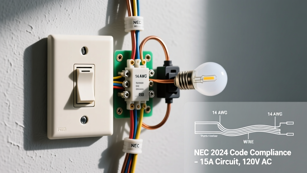
Understanding a basic wiring diagram for light switch installations is the foundational skill for any residential electrical project. Whether you are replacing a worn-out toggle switch or upgrading to a modern smart dimmer, the underlying physics and circuit topology remain consistent. A standard single-pole switch controls a lighting load from one location, interrupting the ungrounded (hot) conductor while leaving the grounded (neutral) conductor continuous to the fixture.
In 2026, adherence to the latest National Electrical Code (NEC) revisions is not just a legal requirement but a critical safety measure. According to the National Fire Protection Association (NFPA), improper switch wiring and loose terminal connections remain leading causes of residential electrical fires. This reference guide breaks down the exact schematic layout, wire mapping, and physical execution required for a code-compliant installation.
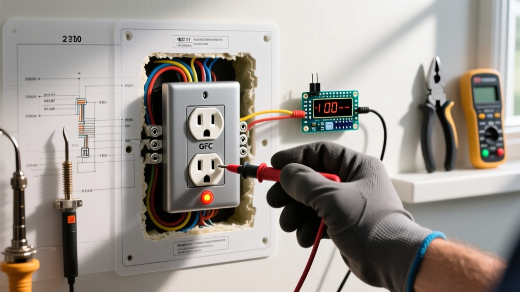
⚠️ SAFETY & CODE WARNING: Always deactivate the circuit at the main breaker panel and verify zero voltage using a non-contact voltage tester (NCVT) and a digital multimeter before opening any junction box. The Occupational Safety and Health Administration (OSHA) mandates strict lockout/tagout procedures for electrical work to prevent arc flash and electrocution hazards.
Anatomy of a Basic Wiring Diagram for Light Switch
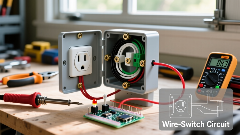
A standard single-pole circuit diagram consists of four primary conductors interacting across three nodes: the breaker panel, the switch box, and the light fixture. The diagram dictates that the switch must only break the "hot" leg. Switching the neutral is a severe code violation that leaves the fixture energized even when the light is off, posing a lethal shock hazard during bulb changes.
Wire Color Coding & Terminal Mapping
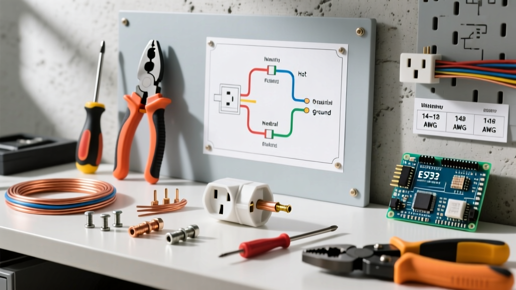
The following table maps the standard NM-B (Romex) cable wire colors to their respective diagram functions and terminal destinations.
| Wire Color | Diagram Function | Switch Terminal | Fixture Connection |
|---|---|---|---|
| Black (or Red) | Ungrounded (Hot) Line / Load | Brass Screw (Line & Load) | Black Fixture Wire |
| White | Grounded (Neutral) Return | Bypassed (Wire-nutted) | White Fixture Wire |
| Bare / Green | Equipment Grounding Conductor | Green Ground Screw | Green Fixture Wire / Box |
The Modern Switch Loop: NEC Article 404.2(C)
Historically, electricians used a 2-wire cable (14/2 or 12/2) to create a "switch loop" between the ceiling fixture and the wall switch. In this legacy diagram, the white wire was re-identified with black tape and used as the hot feed down to the switch, while the black wire carried the switched load back up. This meant no neutral wire was present in the switch box.
However, the proliferation of smart switches, Wi-Fi dimmers, and occupancy sensors—which require a continuous 120V neutral to power their internal radios—forced a code change. The NEC now mandates that a neutral conductor must be available at virtually all switch locations. Therefore, a modern basic wiring diagram for light switch loops must utilize a 3-wire cable (14/3 or 12/3), bringing the hot, the switched load, and the neutral down to the switch box, even if a standard mechanical switch does not immediately use the neutral.
Step-by-Step Physical Wiring Execution
Translating the diagram into physical reality requires precision. Poor mechanical connections increase resistance, leading to thermal buildup and eventual failure.
- Strip the Insulation: Use the built-in strip gauge on the back of the switch. For 14 AWG wire, strip exactly 5/8 inch. For 12 AWG wire, strip 3/4 inch. Exposing too much bare copper creates a shock hazard; too little causes the screw to bite into the insulation.
- Form the J-Hook: Using needle-nose pliers, bend the bare copper into a tight "J" hook. The hook must be oriented clockwise. When you tighten the terminal screw (which turns clockwise), it will pull the loop tighter rather than pushing it out.
- Torque the Terminals: Manufacturer specifications for standard 15A switches (like the Leviton Decora R62-05601-2WS) require 12 to 16 inch-pounds of torque. Use a calibrated torque screwdriver to prevent under-tightening (which causes arcing) or over-tightening (which strips the brass threads).
- Grounding the Box: If you are using a metal junction box, the bare ground wire must first pigtail to the box's green grounding screw before continuing to the switch's green ground screw. Plastic boxes only require the ground to terminate at the switch.
Smart Switch Diagram Variations
When upgrading from a standard toggle to a smart switch (e.g., Lutron Caseta or Leviton Decora Smart), the basic wiring diagram expands. Smart switches require three distinct connections to function:
- Line (Hot): Constant 120V power from the breaker.
- Load: The switched leg going to the light fixture.
- Neutral: The return path to complete the 120V circuit for the switch's internal microprocessor and Wi-Fi/Zigbee radio.
If your existing diagram reflects a legacy 2-wire switch loop without a neutral, you cannot install a standard smart switch without pulling new 3-wire cable or utilizing specialized "no-neutral" smart switches that rely on trickle current through the LED bulb (which often causes flickering in 2026's low-wattage LED fixtures).
Troubleshooting Diagram Discrepancies
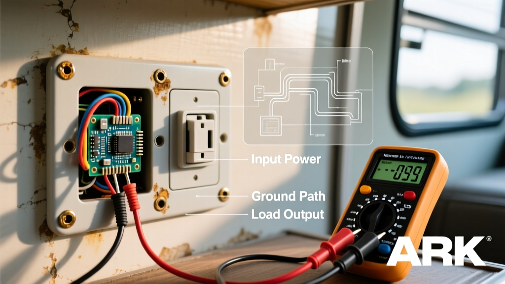
When a circuit fails to operate as the diagram dictates, systematic troubleshooting is required. The Consumer Product Safety Commission (CPSC) advises against guessing electrical faults. Use a digital multimeter (DMM) to verify the following failure modes:
- Reversed Polarity (Switching the Neutral): If the light turns off but a non-contact voltage tester still detects voltage at the fixture socket, the switch is incorrectly wired on the neutral leg. The hot and load wires at the switch must be swapped.
- Floating Ground: If touching the metal faceplate screw yields a mild tingle, the equipment grounding conductor is disconnected or has high resistance. Measure continuity between the switch ground screw and the main panel ground bus; it should read near 0.0 ohms.
- Voltage Drop on Load: If the lights dim significantly when turned on, check for a loose neutral connection in the ceiling junction box. A loose neutral forces the return current to seek alternative paths, creating a severe fire hazard.
2026 Material & Tool Cost Breakdown
Budgeting for a professional-grade switch installation requires accounting for code-compliant materials and precision tools. Below is a realistic cost matrix for a single-pole upgrade in 2026.
| Item / Tool | Specification / Model | Estimated Cost (USD) |
|---|---|---|
| Single Pole Switch | Leviton 15A Decora (R62-05601-2WS) | $3.50 - $5.00 |
| Smart Dimmer Switch | Lutron Caseta (PD-6WCL-WH) | $55.00 - $65.00 |
| Wire Connectors | Ideal WireNuts (Yellow/Red) | $0.15 / each |
| Torque Screwdriver | Wiha 12-16 in-lb Insulated | $45.00 - $60.00 |
| Digital Multimeter | Fluke 117 True-RMS | $190.00 - $210.00 |
Final Verification
Once the physical wiring matches the schematic, restore power at the breaker. Test the switch operation, verify the faceplate sits flush without bowing (which indicates overcrowded wires in the box), and ensure no audible buzzing or excessive heat emanates from the switch yoke after 15 minutes of continuous operation. Mastering the basic wiring diagram for light switch circuits ensures your home's electrical infrastructure remains safe, efficient, and ready for modern smart-home integrations.