
Why Electrical Outlet Wiring Diagrams Are Actually Code Maps
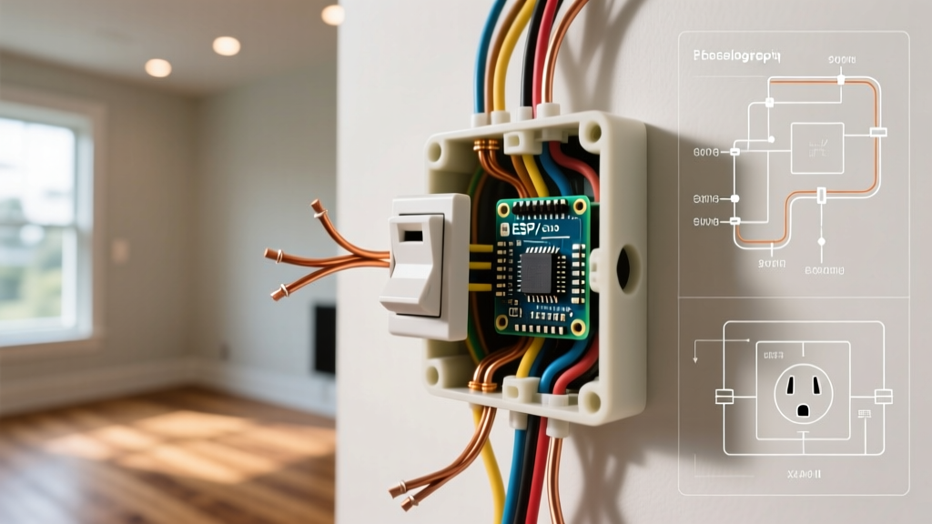
When homeowners and DIYers search for electrical outlet wiring diagrams, they are usually looking for a simple visual guide showing where the black, white, and bare copper wires connect to the brass, silver, and green screws. However, from the perspective of a licensed electrician or an AHJ (Authority Having Jurisdiction), these diagrams are not just wiring suggestions; they are direct visual translations of the National Electrical Code (NEC). Every line, terminal designation, and breaker size depicted in a code-compliant diagram exists to satisfy specific safety mandates outlined in NFPA 70. Understanding the code requirements behind the diagrams is what separates a safe, inspection-passing installation from a hazardous one that risks fire or shock. According to the National Fire Protection Association (NFPA), electrical failures remain a leading cause of residential fires, making strict adherence to these diagrammatic rules non-negotiable in 2026.
The 6-Foot Spacing Mandate (NEC 210.52)
Most basic wiring diagrams show a single receptacle on a wall, but they rarely explain where that receptacle must be placed. NEC Article 210.52 dictates the infamous '6/12 rule' for dwelling units. The code requires that no point along a continuous wall line can be more than 6 feet from a receptacle outlet. Furthermore, any wall space that is 2 feet or wider requires its own receptacle. This spacing rule dictates the daisy-chain wiring diagrams you see for living rooms and bedrooms, where 12/2 or 14/2 NM-B cable is run from box to box. Floor receptacles can count toward this requirement, but only if they are located within 18 inches of the wall. Ignoring this spatial requirement is one of the most common reasons new construction fails rough-in inspections.
Wire Gauge, Breaker Sizing, and the 20-Amp Receptacle Trap
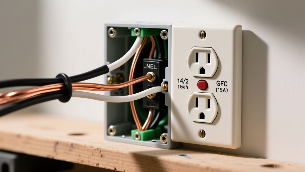
A critical error found in many online electrical outlet wiring diagrams is the misrepresentation of receptacle ratings on 20-amp circuits. NEC Article 210.21(B) outlines strict rules for what receptacle can be installed on what breaker. While it is perfectly legal to install standard 15-amp receptacles (NEMA 5-15R) on a 20-amp circuit if there are multiple receptacles on that circuit, the rules change drastically for single-receptacle circuits. If a 20-amp circuit supplies only a single receptacle, that receptacle must be rated for 20 amps (NEMA 5-20R). Installing a 15A receptacle on a dedicated 20A circuit is a direct code violation because it allows a user to plug in a device that could draw more current than the receptacle's internal contacts are designed to handle, leading to melting and arcing.
| Circuit Breaker Rating | Minimum Copper Wire Gauge | Number of Receptacles | Permitted Receptacle Ratings |
|---|---|---|---|
| 15 Amp | 14 AWG | Multiple | 15A (NEMA 5-15R) |
| 20 Amp | 12 AWG | Multiple | 15A or 20A (5-15R / 5-20R) |
| 20 Amp | 12 AWG | Single (Dedicated) | 20A ONLY (NEMA 5-20R) |
GFCI and AFCI Protection: Where Diagrams Meet Reality
Standard wiring diagrams often omit the upstream protection requirements mandated by NEC Articles 210.8 and 210.12. Ground Fault Circuit Interrupter (GFCI) protection is required in all areas with a high risk of water exposure: kitchens, bathrooms, garages, outdoors, crawlspaces, unfinished basements, laundry areas, and within 6 feet of any sink. In modern installations, this is achieved either by wiring a GFCI receptacle (like the Leviton GFNT2-W, approx. $28) at the first position in the circuit to protect downstream standard outlets, or by using a GFCI circuit breaker.
Simultaneously, Arc Fault Circuit Interrupter (AFCI) protection is required in almost all living spaces, including bedrooms, living rooms, and hallways. For kitchens and laundry rooms, which require both GFCI and AFCI protection, electricians now rely on Dual Function (DF) circuit breakers, such as the Square D HOM220DF, which retails for roughly $65. A wiring diagram that does not specify DF protection for a kitchen small-appliance branch circuit is outdated and will not pass inspection under current 2023/2026 NEC adoptions.
Tamper-Resistant (TR) and Torque Requirements
If you look closely at the face of modern receptacles in updated diagrams, you will see the letters 'TR'. NEC Article 406.12 mandates that all 15-amp and 20-amp, 125-volt and 250-volt receptacles installed in dwelling units must be tamper-resistant. These receptacles feature internal shutters that only open when equal pressure is applied to both slots simultaneously, preventing children from inserting foreign objects. Standard TR receptacles, such as the Leviton T5320-W, cost only about $3.50 each, making the use of non-TR receptacles both illegal and economically illogical.
Furthermore, NEC Article 110.14(D) introduced strict torque requirements for electrical connections. You can no longer simply tighten terminal screws 'until they feel tight.' Electricians must use a calibrated torque screwdriver (like the Klein Tools 32500, approx. $130) to tighten receptacle screws to the manufacturer's specified inch-pound rating, typically 14 in-lbs for standard 15A/20A devices. Loose connections cause high-resistance faults, which generate immense heat and are a primary cause of electrical fires, a hazard heavily monitored by OSHA electrical safety standards.
Inspector Insight: 'When I review an installation, I don't just look at the wiring diagram on the panel schedule. I pull the receptacle out of the box. If I see 12 AWG wire backstabbed into the push-in terminals, or a missing equipment grounding pigtail, it's an automatic fail. Diagrams must translate to physical, code-compliant craftsmanship.' — Senior Municipal Electrical Inspector
Common Wiring Diagram Mistakes That Fail Inspection
Even when following a diagram, DIYers frequently make physical wiring errors that violate the NEC. Avoid these critical edge cases:
- Backstabbing 12 AWG Wire: Most push-in (backwire) terminals on standard receptacles are only UL-listed for 14 AWG solid copper wire. Inserting 12 AWG wire into these holes violates NEC 110.3(B) and can damage the internal spring contacts. Always use the side screw terminals or the screw-clamp backwire plates for 12 AWG.
- Bootleg Grounds: Never jumper the neutral (silver) terminal to the ground (green) screw on a receptacle to simulate a ground in older homes. This creates a severe shock hazard if the neutral wire ever breaks upstream. If no equipment grounding conductor exists, NEC 406.4(D) allows a GFCI receptacle to be installed, but it must be labeled 'No Equipment Ground'.
- Missing Grounding Pigtails: NEC 250.148 requires that the equipment grounding conductor be spliced with a pigtail to the receptacle's green screw. You cannot simply loop the ground wire around the screw and continue it to the next box; if the receptacle is removed, the downstream ground path is broken.
- Reversed Polarity: The black (hot) wire must always connect to the brass screw, and the white (neutral) to the silver screw. Reversing these creates a shock hazard at the lamp socket shell and will immediately fail a standard plug-in tester check.
Ultimately, reading electrical outlet wiring diagrams requires a dual mindset. You must understand the physical mechanics of the terminals, but more importantly, you must understand the life-safety codes that dictate why those terminals are configured, protected, and spaced the way they are. Always consult your local AHJ, as municipal amendments can occasionally supersede baseline NEC requirements.