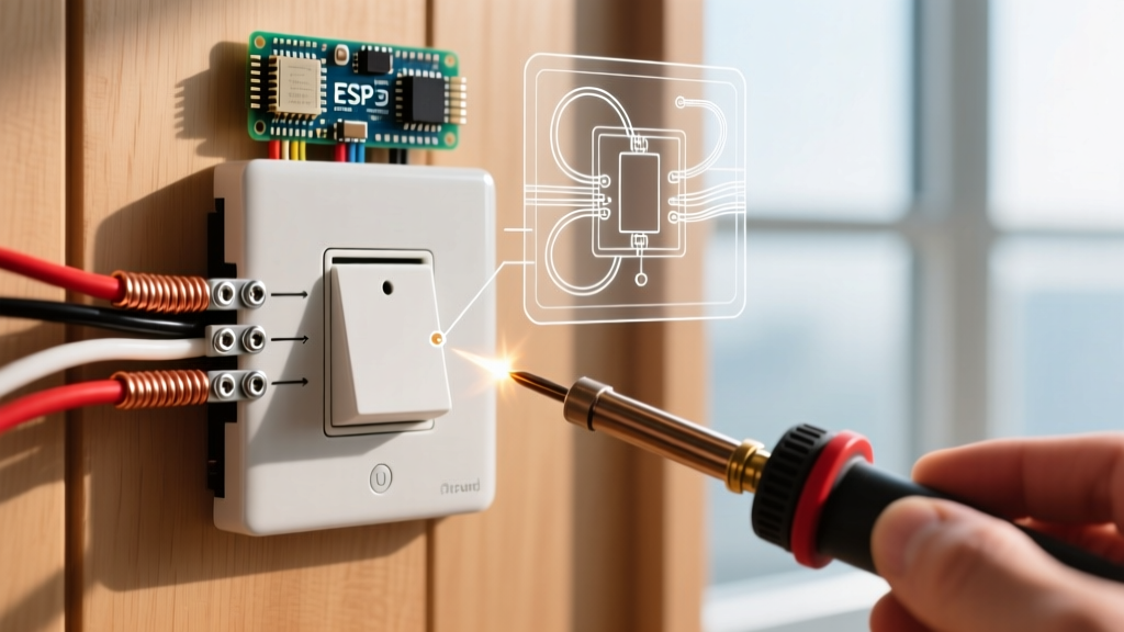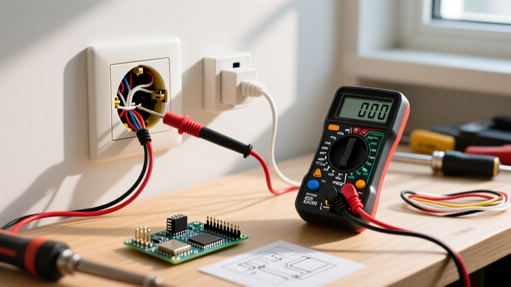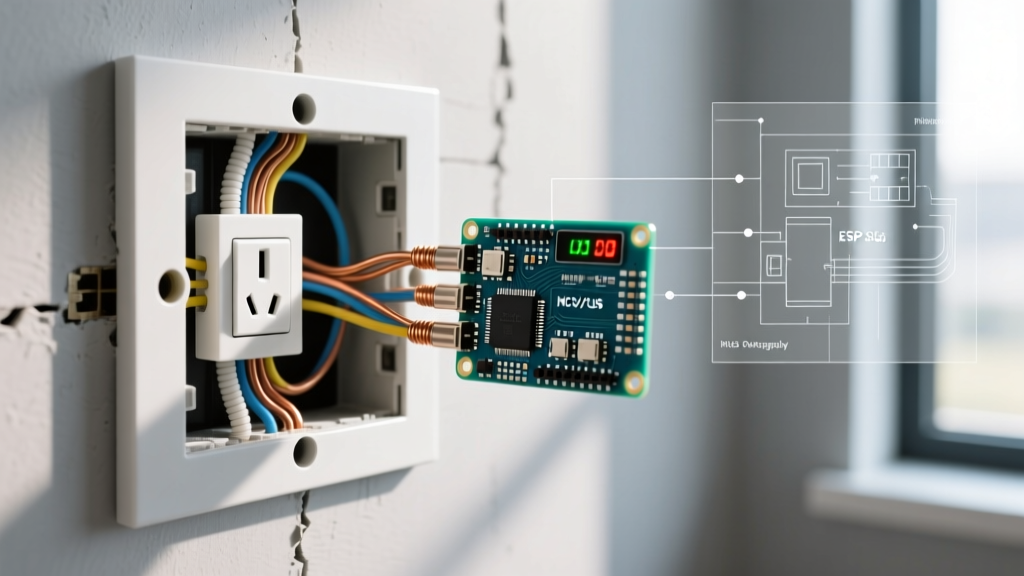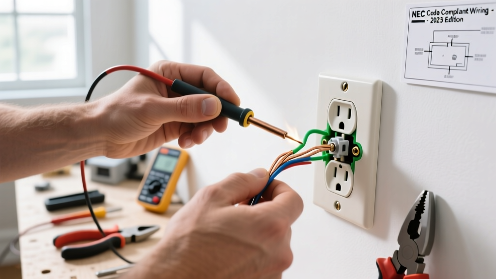

The Reality of Putting a Camera in an Electrical Outlet
When DIYers and security enthusiasts search for how to install a camera in electrical outlet configurations, they are typically trying to achieve a clean, wire-free aesthetic for their home security system. However, the internet is flooded with dangerous advice regarding 'spy cameras' disguised as outlets, as well as poorly conceived tutorials that suggest cramming 12V DC transformers into the same junction box as 120V AC mains. As a licensed electrical knowledge hub, ElectricalFlux must set the record straight for 2026: mixing low-voltage camera circuitry with high-voltage mains inside a single, undivided enclosure is a severe fire hazard and a direct violation of the National Electrical Code (NEC).
This wiring diagram reference will guide you through the code-compliant method of powering a security camera directly from an outlet circuit. We will cover how to use divided junction boxes, recessed outlet enclosures, and proper 120V-to-12V step-down transformers to achieve a hidden power supply without violating safety standards or voiding your home insurance.
NEC Code Violations: Why Mains and Low-Voltage Don't Mix
Before touching a wire stripper, you must understand the legal and safety boundaries of integrating security cameras with mains power. According to the National Fire Protection Association (NFPA), which publishes the NEC, low-voltage circuits (Class 2 and Class 3, which include most 12V/24V security cameras) must be physically separated from power circuits.
NEC Article 725.136 (Separation of Conductors): Class 2 and Class 3 circuit conductors shall not be placed in any cable, cable tray, compartment, enclosure, manhole, outlet box, device box, raceway, or similar fitting with conductors of electric light, power, and Class 1 circuits unless a physical barrier is installed.
If you purchase a commercial 'hidden spy camera' that replaces a standard duplex receptacle faceplate, these devices are typically UL-listed only if their internal low-voltage components are completely encapsulated and isolated from the mains terminals by the manufacturer. However, if you are hardwiring a custom security camera (like a Hikvision or Amcrest PoE/DC model) and plan to stuff a generic 12V power brick into the wall cavity alongside your Romex 14/2 or 12/2 wiring, you are creating a massive thermal and shock hazard.
The Interference Factor
Beyond safety, placing a Wi-Fi-enabled camera directly inside a standard PVC or metal outlet box surrounded by 120V AC wiring results in severe electromagnetic interference (EMI). The alternating current creates a magnetic field that can degrade the camera's wireless signal, causing dropped frames and latency in your security feed.
The Code-Compliant Solution: Recessed & Divided Boxes
To properly wire a camera into an electrical outlet circuit, you must use specialized enclosures designed to separate the voltages or provide adequate depth for a factory-sealed transformer. Below are the two industry-standard methods for 2026.
Method 1: The Recessed Media Box (Arlington DVFR2W)
The Arlington Industries DVFR2W (approx. $28.00) is a non-metallic, recessed TV box that provides extra depth. While primarily used for TV power cords, it is ideal for plugging in a compact, UL-listed 12V camera power adapter (like the Mean Well GST40A12) and routing the low-voltage wire out through a separate low-voltage brush plate. The mains receptacle remains isolated in its own standard yoke.
Method 2: The Divided Junction Box (Carlon B618R)
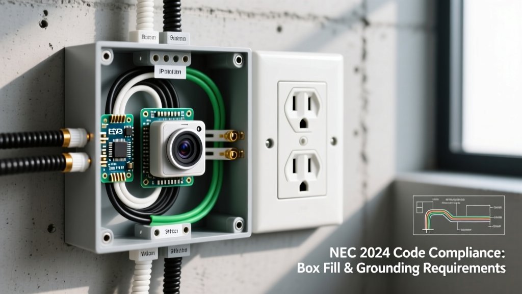
For hardwiring a bare 120V-to-12V DIN-rail transformer (such as the Mean Well HDR-15-12, approx. $22.50) directly into the circuit, you must use a divided box. The Carlon B618R features a physical snap-in barrier that separates the 120V AC splices from the 12V DC terminals, satisfying NEC 725.136.
Wiring Diagram Reference: Hardwiring a 12V Camera Transformer
Below is the textual wiring schematic for integrating a Mean Well HDR-15-12 transformer into a divided junction box to power a standard 12V DC security camera.
Terminal Mapping Schematic
- 120V AC Hot (Black): Connects to Transformer
LTerminal (via WAGO 221-412 lever nut on the divided side). - 120V AC Neutral (White): Connects to Transformer
NTerminal. - 120V AC Ground (Bare/Green): Connects to Transformer
Groundsymbol terminal AND pigtailed to the metal box grounding screw (if using a metal enclosure). - Transformer V+ (Red): Connects to Camera Positive (+) wire.
- Transformer V- (Black): Connects to Camera Negative (-) wire.
Note: Always use a 3A inline fuse on the V+ line near the transformer to protect the camera's internal board from power surges originating from the mains grid.
Box Fill Calculations: Sizing Your Enclosure
One of the most common failures in DIY camera wiring is 'box stuffing.' Overcrowding an outlet box causes heat buildup, which degrades wire insulation and trips breakers. According to the Electrical Safety Foundation International (ESFI), adhering to NEC Article 314.16 for box fill is non-negotiable.
| Wire Gauge (AWG) | Volume Required per Conductor | Typical Camera Circuit Application |
|---|---|---|
| 14 AWG | 2.0 Cubic Inches | 15A Mains circuits (Romex 14/2) |
| 12 AWG | 2.25 Cubic Inches | 20A Mains circuits (Romex 12/2) |
| 18 AWG (Low Voltage) | Exempt (Class 2) | Camera DC power leads (Must be separated by barrier) |
Calculation Example: If you are bringing one 14/2 Romex cable into the AC side of a divided box to feed a receptacle and the transformer, you have 2 current-carrying conductors (Hot, Neutral) + 1 Ground + 1 Internal Clamp + 1 Device (Receptacle) = 5 volume allowances.
5 x 2.0 cu in = 10.0 Cubic Inches minimum required just for the AC side. Ensure your divided box offers at least 12-14 cubic inches per side to accommodate the physical bulk of the transformer.
Step-by-Step Installation Guide
- Kill the Power: Turn off the 15A or 20A breaker at the main panel. Verify the absence of voltage using a non-contact tester like the Klein Tools NCVT-4IR ($35.00).
- Prepare the Enclosure: If using a Carlon divided box, snap the isolation barrier firmly into the center track. Ensure no gaps exist where a stray 18AWG wire could cross into the 120V zone.
- Strip and Terminate Mains: Strip 3/4 inch of insulation from the 14 AWG Romex. Use WAGO 221-412 lever connectors to splice the line voltage to the transformer's AC input and the downstream receptacle. Lever nuts save immense space compared to traditional wire nuts, which is critical in camera power boxes.
- Mount the Transformer: Secure the Mean Well transformer to the DIN rail or screw-mount it to the back of the low-voltage side of the box.
- Route the Low-Voltage Wire: Run an 18AWG 2-conductor low-voltage wire from the transformer's DC output terminals, out through a separate knockout, and up the wall cavity to the camera mounting location.
- Torque Verification: Use a torque screwdriver set to the manufacturer's spec (usually 7-9 in-lbs for standard receptacle terminal screws) to ensure the outlet faceplate is secure and won't arc under load.
Troubleshooting Common Power Delivery Issues
Even with a perfect wiring diagram, integrating cameras into outlet circuits can present unique electrical gremlins. Here is how to diagnose them:
- Camera Reboots Randomly at Night: This is classic voltage drop. When the camera's IR (Infrared) cut filter engages at dusk, the LED array draws a sudden spike in amperage (often jumping from 300mA to 1.2A). If your 18AWG low-voltage wire run exceeds 15 feet, the voltage at the camera end will drop below 11V, causing a brownout reboot. Fix: Upgrade the low-voltage run to 16AWG or 14AWG wire, or move the transformer closer to the camera.
- Ground Loop Interference (Analog/Coax Cameras): If you are wiring an older analog camera and see rolling horizontal bars on the feed, you have a ground loop. This happens when the camera's ground and the DVR's ground are at slightly different potentials due to sharing a circuit with heavy appliances. Fix: Install a ground loop isolator on the coax line, or ensure the camera's 12V DC power supply is completely floating (ungrounded DC output).
- Wi-Fi Signal Degradation: As mentioned, 120V AC wiring acts as an antenna for EMI. If your wireless camera is mounted directly over the outlet box, the signal may drop. Fix: Use a 5GHz Wi-Fi channel (which penetrates drywall better but suffers less from 60Hz mains harmonic interference) or switch to a hardwired PoE (Power over Ethernet) setup using a PoE injector located at the router.
Frequently Asked Questions
Can I use a commercial 'Spy Camera' disguised as an outlet?
If the device is a UL-listed plug-in gadget that simply looks like an outlet faceplate but plugs into an existing standard receptacle, it is generally safe to use, provided it doesn't block the grounding pin or overheat. However, hardwiring the internal guts of a spy camera into your wall's mains box is illegal, uninsurable, and highly dangerous.
Do I need a permit to wire a camera power supply into an outlet?
Yes. Any modification to your home's 120V AC wiring, including adding a new junction box, hardwiring a transformer, or replacing an outlet to accommodate a camera power feed, requires an electrical permit in most municipalities. Low-voltage wire routing (the 12V side) typically does not require a permit, but the mains side absolutely does.