
Understanding the Wiring Diagram for Single Pole Light Switch Circuits
The single pole light switch is the most fundamental and ubiquitous control device in residential and commercial electrical systems. It controls a lighting fixture or a dedicated appliance from a single physical location. While the physical installation is straightforward, a thorough comprehension of the underlying circuitry is what separates a safe, code-compliant installation from a dangerous fire hazard. In this guide, we will dissect the standard wiring diagram for single pole light switch configurations, provide exact tool recommendations for 2026, and walk through a meticulous, step-by-step installation process aligned with the latest National Electrical Code (NEC) standards.
Before touching a single wire, it is critical to understand that a standard single pole switch does not interrupt the neutral conductor. According to National Fire Protection Association (NFPA) guidelines, specifically NEC Article 404.2(B), switches must not disconnect the grounded (neutral) conductor unless all ungrounded (hot) conductors are simultaneously disconnected. The switch solely acts as a mechanical break in the ungrounded 'hot' pathway.
Safety Warning: Electrical work carries inherent risks of severe shock, arc flash, and fire. Always verify that the circuit is de-energized using a calibrated non-contact voltage tester and a multimeter before beginning any work. For comprehensive safety protocols, refer to the Electrical Safety Foundation International (ESFI) guidelines on residential electrical safety.
Essential Tools and Materials (2026 Pricing & Specs)
Using the correct tools ensures clean wire terminations and prevents damaged conductors. Here is the exact toolkit required for a professional-grade single pole switch installation:
- Voltage Tester: Fluke 2AC VoltAlert Non-Contact Voltage Tester ($38). Essential for initial dead-front verification.
- Wire Strippers: Klein Tools 11055 10-20 AWG Solid Wire Strippers ($32). Provides precise stripping without nicking the copper core.
- Multimeter: AstroAI Digital Multimeter ($25). Used for secondary verification of zero voltage between hot and ground.
- Switch Device: Leviton 1451-2W 15 Amp, 120-Volt Single Pole Toggle Switch ($3.50) or Leviton 5601-2W Decora Rocker Switch ($6.00). Both are UL-listed and feature side-wiring terminals.
- Screwdrivers: Wiha 320P Precision Phillips and Slotted drivers ($18). Magnetic tips prevent dropped terminal screws inside the junction box.
Wire Gauge and Breaker Matching Matrix
Before wiring, you must verify the circuit's wire gauge matches the breaker size. Mismatching these is a severe NEC violation and a primary cause of residential electrical fires.
| Circuit Breaker Size | Wire Gauge (Copper) | Max Continuous Load | Switch Rating Required |
|---|---|---|---|
| 15 Amp | 14 AWG | 12 Amps (1,440W) | 15A / 120V |
| 20 Amp | 12 AWG | 16 Amps (1,920W) | 20A / 120V |
Anatomy of the Wiring Diagram
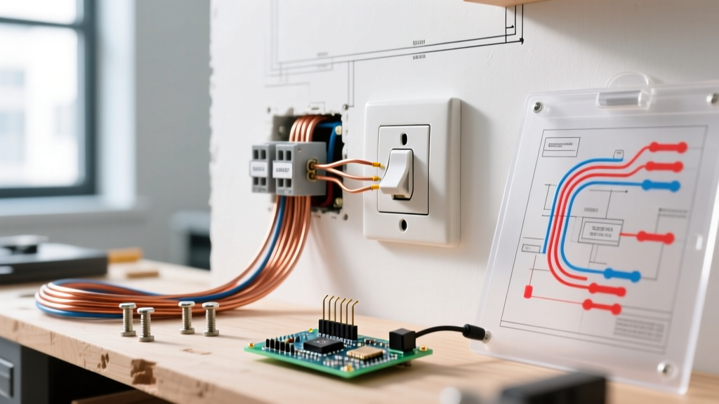
When you look at a standard wiring diagram for single pole light switch setups, you will identify four distinct wire types interacting within the wall cavity and the ceiling junction box:
- Line (Hot): The continuous ungrounded conductor (usually black) bringing 120V power from the breaker panel to the switch box.
- Load (Switched Hot): The ungrounded conductor (often black or red) carrying power from the switch to the light fixture. This wire is only energized when the switch is in the 'ON' position.
- Neutral (Grounded): The white conductors. In a standard single pole switch loop, the neutrals bypass the switch entirely. They are wire-nutted together in the back of the switch box and travel directly to the light fixture to complete the circuit.
- Ground (Equipment Grounding Conductor): Bare copper or green insulated wires. These bond the metal switch box, the switch yoke, and the light fixture to earth ground, providing a safe path for fault currents.
Step-by-Step Installation Procedure
Step 1: Power Isolation and Verification
Navigate to your main electrical panel and turn off the breaker corresponding to the lighting circuit. Do not rely solely on wall switches being in the 'off' position. Place a piece of electrical tape over the breaker (a rudimentary lockout/tagout method) to prevent accidental re-engagement. Insert the Fluke 2AC VoltAlert into the gap around the old switch plate. If it remains silent, proceed. Remove the faceplate and switch mounting screws, pull the switch out gently, and test directly across the terminal screws and the ground wire with your multimeter set to AC Voltage. It must read 0.0V.
Step 2: Disconnect and Inspect Existing Wiring
Loosen the terminal screws and disconnect the wires. If the previous installer used 'backstab' push-in connections, you will need to release the tension using a small flathead screwdriver or simply cut the wires back to the jacket. Inspect the exposed copper. If it is pitted, corroded, or deeply grooved from previous terminal screws, use your Klein Tools wire strippers to cut back to fresh wire and re-strip.
Step 3: Precision Wire Preparation
Strip exactly 3/4-inch of insulation from the Line, Load, and Ground wires. Stripping too little leaves exposed copper outside the terminal saddle (a shock hazard); stripping too much exposes bare wire past the screw head (a short-circuit hazard). Using needle-nose pliers, form a perfect 'shepherd's hook' (J-hook) at the end of each stripped wire.
Step 4: Terminating the Connections
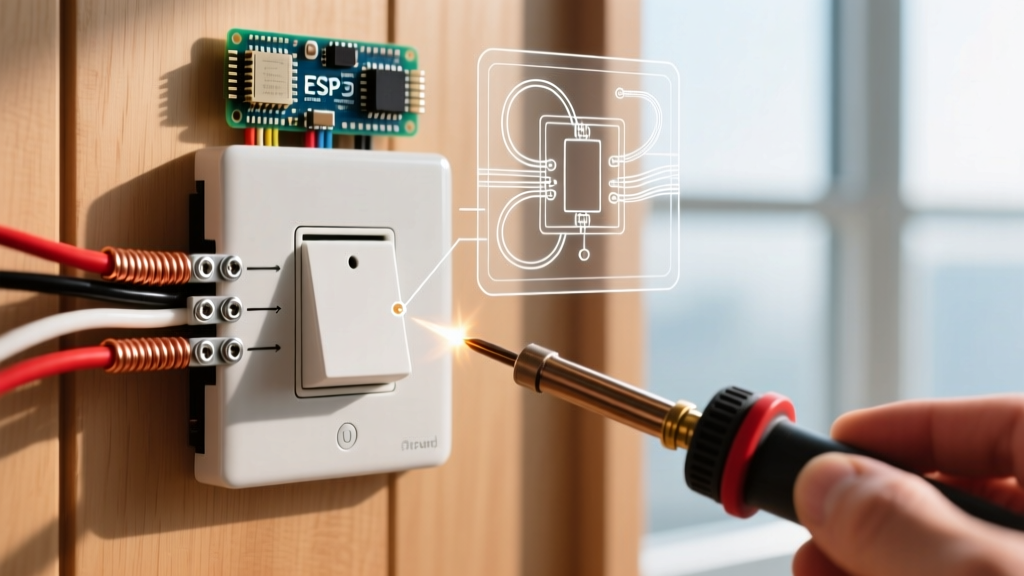
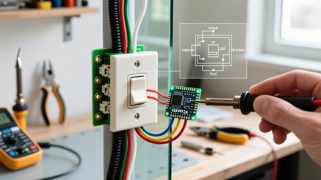
This is where the wiring diagram for single pole light switch configurations comes to life. Always use the side-wiring terminal screws, never the push-in backstab holes. Backstab connections rely on a small internal spring clip that loosens over years of thermal cycling, leading to high-resistance arcing and melted plastic housings.
- Ground: Wrap the bare copper ground wire clockwise around the green grounding screw on the switch yoke. Tighten firmly.
- Line (Hot): Wrap the black Line wire clockwise around one of the brass terminal screws. The clockwise direction ensures that tightening the screw pulls the wire loop tighter rather than pushing it out.
- Load (Switched Hot): Wrap the remaining black (or red) Load wire clockwise around the second brass terminal screw.
Expert Note: On a standard single pole switch, the two brass screws are internally connected through the mechanical toggle. Unlike a 3-way switch, line and load are interchangeable on the brass terminals of a single pole switch, though maintaining consistency (Line on bottom, Load on top) is considered best practice for future troubleshooting.
Step 5: Box Dressing and Mounting
Gently fold the wires back into the junction box. Push the ground wires deep into the back corners first, followed by the bundled neutrals, and finally the Line and Load wires. Seat the switch yoke flush against the drywall or plaster ring. Use the provided mounting screws, ensuring the switch is perfectly plumb using a small torpedo level. Secure the faceplate, being careful not to overtighten the 6-32 faceplate screws, which can crack standard nylon plates.
Common Edge Cases and Troubleshooting
Even with a perfect understanding of the wiring diagram, older homes present unique challenges. Here are three common edge cases you may encounter:
The 'Switched Neutral' Hazard
If you turn off the switch, but a non-contact voltage tester still detects voltage at the light fixture's socket, the original electrician likely switched the neutral instead of the hot wire. This means the fixture is constantly energized at 120V, waiting for a neutral path to illuminate. This is a severe shock hazard when changing bulbs and violates NEC 404.2(B). You must rewire the circuit at the ceiling junction box to ensure the black hot wire routes through the switch, and the white neutral connects directly to the fixture.
Ghost Voltage on the Load Wire
When testing the Load wire with the switch off, a high-impedance digital multimeter might read 40V to 70V. This is 'ghost voltage' caused by capacitive coupling from adjacent live wires running parallel in the same wall cavity. To verify it is ghost voltage, switch your multimeter to a low-impedance (LoZ) setting, or use an analog solenoid tester (Wiggy). The ghost voltage will instantly drop to 0V under a real load.
Smart Switch Upgrades
If you plan to upgrade to a smart switch (like the Leviton Decora Smart Wi-Fi D215S), the standard wiring diagram changes. Smart switches require a continuous 120V power source for their internal radios and LEDs. Therefore, you must have a neutral wire available in the switch box. If your box only contains Line, Load, and Ground (a classic 'switch loop'), you cannot install a standard neutral-requiring smart switch without pulling new cable or using a specialized 'no-neutral' smart switch, which often requires installing a bypass capacitor at the light fixture to prevent LED flickering.
Final Inspection and Testing
Once the faceplate is installed and the breaker is restored, test the mechanical operation of the toggle. The light should illuminate instantly without flickering or buzzing. A buzzing sound typically indicates a loose wire termination causing micro-arcing at the screw head, or a dimmer switch that is incompatible with the installed LED drivers. If any buzzing is present, immediately kill the breaker, remove the faceplate, and re-torque the terminal screws.
By strictly adhering to the wiring diagram for single pole light switch principles and utilizing professional-grade termination techniques, you ensure a safe, durable, and code-compliant electrical installation that will operate flawlessly for decades. For further reading on residential wiring safety and DIY best practices, consult the resources provided by the U.S. Consumer Product Safety Commission (CPSC).