
The Critical Importance of Code-Compliant Switch Wiring
According to the U.S. Consumer Product Safety Commission (CPSC), electrical receptacles and switches are involved in thousands of residential fires annually. While a standard wiring diagram for a single pole light switch seems elementary, improper terminations, ignored box fill calculations, and ungrounded yokes are leading culprits in arc faults and thermal runaway. As of the 2023 NEC (and adopted into 2026 local amendments), the margin for error in residential wiring has strictly narrowed.
This guide transcends basic DIY tutorials. We will dissect the exact National Electrical Code (NEC) requirements, torque specifications, and failure modes associated with single-pole switch installations.
Anatomy of a Compliant Single Pole Setup
Before consulting the wiring diagram for a single pole light switch, verify your materials meet modern safety thresholds. Avoid builder-grade components that lack robust terminal clamps.
- Switch: Eaton 1201V (15A, 120/277V AC) or Leviton 1451-2W. Both feature heavy-duty brass terminal screws and reinforced steel yokes.
- Wire: 14/2 NM-B (Romex) for 15A circuits; 12/2 NM-B for 20A circuits. Never mix 14 AWG wire on a 20A breaker.
- Box: Carlon B618R (18 cubic inch PVC) or an equivalent deep metal box to accommodate modern smart switches or dimmers.
- Connectors: IDEAL Wire-Nut 72B (yellow) or WAGO 221-412 lever nuts for splicing neutrals and grounds.
Step-by-Step Wiring Diagram for a Single Pole Light Switch
The fundamental logic of a single pole switch is to interrupt the ungrounded (hot) conductor while allowing the grounded (neutral) conductor to pass continuously to the load. Here is the precise sequence for a standard line-to-load configuration:
- De-energize and Verify: Turn off the breaker. Use a Klein Tools NCVT-2 non-contact voltage tester and a CAT III multimeter to confirm 0V between hot, neutral, and ground.
- Prepare the Conductors: Strip exactly 3/4 inch of insulation from the black (hot) and white (neutral) wires using a precision stripper. Do not nick the copper, which creates a stress fracture and future failure point.
- Splice Neutrals and Grounds: The white neutral wires from the line and load cables must be spliced together and pushed to the back of the box. They do not connect to a standard single pole switch. Bond all bare copper ground wires together with a green wire nut, adding a 6-inch pigtail to the metal box (if applicable) and the switch's green grounding screw.
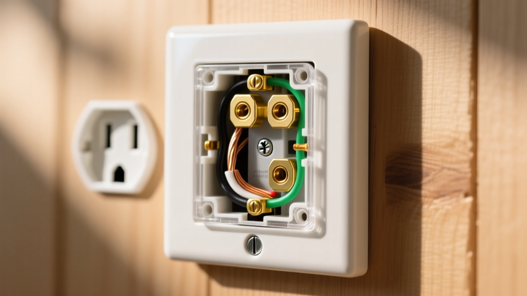
- Terminate the Hot and Load: Connect the line hot (black) to one brass terminal and the load hot (black) to the other brass terminal. Form a clockwise shepherd's hook loop around the screw. Tighten to the manufacturer's specified torque.
- Secure the Yoke: Mount the switch to the box using the provided #6-32 mounting screws. Ensure the yoke sits flush against the drywall or plaster ring to prevent mechanical stress on the terminals.
NEC Code Compliance Matrix
The National Fire Protection Association (NFPA) updates the NEC every three years. Below is a matrix of the most frequently violated articles during single pole switch installations.
| NEC Article | Requirement | Common Field Violation |
|---|---|---|
| 404.9(B) | Switch yokes must be grounded in residential installations. | Omitting the ground pigtail on the green screw to save time. |
| 314.16(B) | Box fill calculations must not exceed the box's cubic inch rating. | Stuffing 5+ cables and a smart switch into a standard 12.5 cu in box. |
| 110.14(D) | Terminations must be torqued to manufacturer specifications. | Hand-tightening screws, leading to thermal expansion and loosening. |
| 250.148 | Equipment grounding conductors must be bonded to metal boxes. | Failing to use a grounding clip or pigtail on metal junction boxes. |
Failure Mode Analysis: Backstab vs. Side Wiring
Expert Warning: Never use the push-in backstab terminals found on the rear of budget switches. While UL-listed, they rely on a small spring-metal clip that makes minimal contact with the wire. Under continuous 12A-15A loads, these connections exhibit high resistance, generating excessive heat and eventually causing arc faults.
Always utilize the side-wiring terminal screws. For an even more secure connection, look for switches featuring back-wire clamps (such as the Leviton Pro Grade line), where a screw tightens a metal plate directly against the inserted straight wire, offering superior pull-out strength and contact area.
Precision Torque: The Missing Link in DIY Wiring
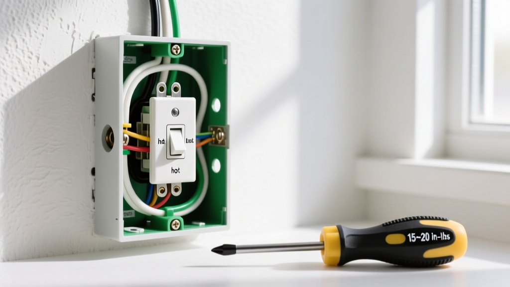
NEC 110.14(D) mandates that electrical connections be torqued to the manufacturer's specifications. While most residential electricians use standard screwdrivers, the transition to smart homes and continuous LED driver loads demands precision. Under-torqued screws loosen over time due to thermal cycling (the heating and cooling of the wire as current flows), leading to high-resistance faults and melted switch yokes.
For the Eaton 1201V and Leviton 1451 series, the specified torque is typically 14 in-lbs. To achieve this, professionals use calibrated torque screwdrivers like the Wiha 64501 or the CDI 401SM. Investing in a torque screwdriver (approximately $45-$60) eliminates guesswork and ensures the brass terminal plate bites securely into the copper conductor without crushing or strand-severing the wire.
Furthermore, when forming the shepherd's hook loop, ensure the insulation jacket stops exactly 1/16th of an inch from the terminal plate. Exposed copper beyond the terminal creates a shock hazard, while insulation caught under the plate causes a high-resistance connection.
Box Fill Calculations: The Overlooked Fire Hazard
Heat dissipation is critical. If a box is overfilled, wires are crushed, damaging insulation and creating short-circuit risks. Let us calculate the box fill for a standard 14 AWG single pole switch setup per NEC Table 314.16(B), which assigns a volume allowance of 2.0 cubic inches per 14 AWG conductor.
- 2 Hot Wires (Line and Load): 2 x 2.0 = 4.0 cu in.
- 2 Neutral Wires (Spliced): 2 x 2.0 = 4.0 cu in.
- 1 Ground Wire (All grounds count as 1): 1 x 2.0 = 2.0 cu in.
- 1 Device (Switch counts as 2 conductors): 2 x 2.0 = 4.0 cu in.
- Total Required Volume: 14.0 cubic inches.
A standard shallow 12.5 cubic inch box is a code violation for this setup. You must use an 18 cubic inch deep box (like the Carlon B618R) to remain compliant and ensure safe thermal dissipation.
Frequently Asked Questions
Can I use a single pole switch on a 20A circuit?
Yes, provided the switch is rated for 20A (e.g., Eaton 1221V) or if the load it controls does not exceed the switch's 15A rating and there are no 20A receptacles on the same downstream circuit. However, best practice dictates matching the switch amperage to the breaker rating.
Does it matter which brass screw gets the line vs. load wire?
For a standard mechanical single pole switch, polarity between the two brass terminals does not matter. The switch simply breaks the circuit. However, if you are installing a smart switch or dimmer with a designated Line and Load terminal, miswiring will cause the device to fail or operate unsafely.
What if my home lacks a ground wire?
If you are replacing an existing switch in an older home with ungrounded (2-wire) NM cable, NEC 404.9(B) Exception 1 allows you to install a replacement switch without an equipment ground, provided you use a GFCI-protected circuit or a faceplate with no exposed conductive parts. However, upgrading the circuit to include a proper ground is highly recommended for modern safety.
By adhering strictly to this wiring diagram for a single pole light switch and respecting NEC parameters, you ensure a resilient, fire-resistant electrical system that will safely operate for decades.