
Why Code Compliance Dictates Your Simple Wiring Diagram for Light Switch
When homeowners and novice DIYers search for a simple wiring diagram for light switch installations, they are often met with outdated schematics that ignore modern safety mandates. Wiring a basic single-pole switch is mechanically straightforward, but doing it in a way that complies with the National Electrical Code (NEC) requires a precise understanding of box fill calculations, grounding continuity, and termination torque. According to the Electrical Safety Foundation International (ESFI), electrical distribution and lighting equipment are responsible for tens of thousands of home structure fires annually, many stemming from loose terminations and overloaded junction boxes.
This guide strips away the fluff and provides a rigorous, code-compliant approach to wiring a standard single-pole light switch. We will focus heavily on the 2023 and upcoming 2026 NEC enforcement trends, ensuring your installation is safe, inspectable, and future-proof.
The NEC 404.2(C) Mandate: The Neutral Wire Requirement
Historically, a basic switch loop only required an ungrounded (hot) conductor and a returning switched-hot conductor. The grounded (neutral) conductor was simply passed through the ceiling junction box directly to the light fixture. This is no longer code-compliant in new construction or major remodels.
NEC Article 404.2(C) explicitly requires that a grounded circuit conductor (neutral) be provided at the switch box. This was introduced to accommodate smart switches, occupancy sensors, and timers that require a continuous 120V standby power source. Even if you are installing a basic, dumb mechanical toggle switch today, you must route the neutral wire down to the switch box and cap it with a wire nut or WAGO connector for future use.
Inspector's Note: If you are doing a like-for-like replacement in an existing home built before this code cycle, you are generally grandfathered in. However, if you are pulling new 14/3 or 12/3 NM-B cable for a new circuit, the neutral must be present in the switch box.
Calculating Box Fill Before You Wire (NEC Article 314)
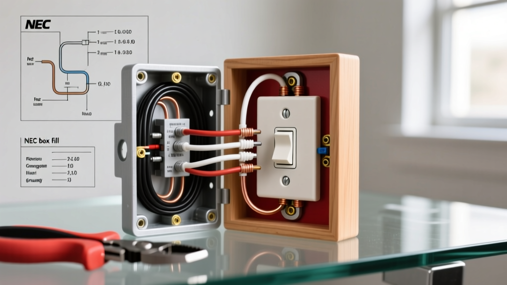
Before executing any simple wiring diagram for light switch setups, you must verify that your electrical box has adequate cubic inch capacity. Overcrowding causes wire insulation damage and traps heat. NEC Article 314.16(B) dictates the math.
Box Fill Math for a Standard Single-Pole Switch
Assume you are using 14 AWG wire (15-Amp circuit) and one 14/2 NM-B cable is entering the box, while another 14/2 NM-B cable is leaving the box to feed the light.
- Current-Carrying Conductors: 4 wires (2 blacks, 2 whites). At 2.0 cubic inches per 14 AWG wire = 8.0 cu in.
- Switch Device: Counts as 2 conductors based on the largest wire connected to it. 2 x 2.0 = 4.0 cu in.
- Equipment Grounding Conductors: All bare/green wires combined count as 1 conductor. 1 x 2.0 = 2.0 cu in.
- Cable Clamps: Internal plastic clamps count as 1 conductor. 1 x 2.0 = 2.0 cu in.
Total Required Volume: 16.0 cubic inches. A standard single-gang 'nail-on' plastic box typically offers 18.0 to 22.5 cubic inches, making this configuration perfectly compliant. If you were using 12 AWG wire (20-Amp circuit), the multiplier jumps to 2.25 cubic inches, requiring a deeper box.
Executing the Simple Wiring Diagram for Light Switch: Step-by-Step
Follow this exact sequence to ensure a safe, professional-grade termination.
Phase 1: Cable and Wire Preparation
- Jacket Stripping: The outer NM-B jacket must enter the box by at least 1/4 inch, but no more than 3/4 inch. Use a romex ripper to avoid nicking the inner THHN insulation.
- Wire Stripping: Strip exactly 3/4 inch of insulation from the black and white wires. If you can see bare copper outside the terminal screw when tightened, the wire is stripped too far (a fire hazard). If the insulation is pinched under the screw head, it will cause a high-resistance connection.
Phase 2: Grounding and Box Bonding
Never rely on the switch's metal yoke to ground a metal electrical box. You must create a continuous grounding path.
- Cut a 6-inch piece of bare 14 AWG or 12 AWG copper wire (matching your circuit).
- Use a green wire nut or a crimp sleeve to join the incoming bare grounds, the outgoing bare grounds, and your pigtail.
- If using a metal box, attach the pigtail to the box using a 10-32 green grounding screw tapped into the back of the box.
- Attach a second pigtail to the green grounding screw on the single-pole switch.
Phase 3: Line, Load, and Torque Termination
A standard single-pole switch does not have a designated 'Line' (source) and 'Load' (to fixture) side; either brass screw can accept either wire. However, for consistency and future troubleshooting, connect the incoming hot (Line) to the bottom brass screw and the outgoing switched-hot (Load) to the top brass screw.
- Form a 'J-hook' in the stripped wire using needle-nose pliers.
- Hook the wire around the brass terminal screw in a clockwise direction. This ensures that as you tighten the screw, the loop pulls tighter rather than pushing out.
- Apply Torque: NEC 110.14(D) requires that terminations be torqued to the manufacturer's specifications. For most residential switches (e.g., Leviton, Lutron), this is between 14 and 16 inch-pounds. Use a calibrated torque screwdriver to secure the connection.
Top Code Violations and Real-World Failure Modes
Understanding where others fail is the best way to ensure your simple wiring diagram for light switch results in a flawless installation. Review the most common violations cited by municipal electrical inspectors.
| Code Violation | NEC Reference | Real-World Failure Mode & Hazard |
|---|---|---|
| Using 'Backstab' Push-In Terminals | 110.14 (Terminations) | The internal spring-steel contacts lose tension over time due to thermal expansion/contraction cycles, leading to arcing, melted plastic housings, and electrical fires. |
| Missing Neutral at Switch Box | 404.2(C) | Prevents the legal installation of smart home switches or motion sensors later, forcing homeowners to illegally bootleg a neutral from the ground wire (a severe shock hazard). |
| Overcrowded Junction Box | 314.16(B) | Wires are crushed against the switch yoke, compromising the THHN insulation and creating a short-circuit path to the metal strap or grounded box. |
| Reversed Grounding Polarity | 250.148 | Connecting the hot wire to the ground screw instantly energizes the faceplate screws and switch toggle, presenting a lethal shock hazard to the user. |
Pro-Tier Tools for Code-Compliant Terminations
You cannot achieve NEC compliance with a dull pocket knife and a standard Phillips screwdriver. Upgrading to professional-grade tools ensures precision and safety.
- Wire Strippers: Klein Tools 11055 (for 10-18 AWG solid wire). Provides clean, exact 3/4-inch strips without scoring the copper conductor.
- Torque Screwdriver: CDI Torque 401SM or Wiha 28501. Pre-set to 14 in-lbs to guarantee perfect terminal pressure without snapping the screw head.
- Push-In Connectors: WAGO 221 Series. Ideal for joining the neutral wires in the back of the box. They are UL-listed, transparent (allowing visual inspection of wire seating), and take up significantly less box volume than traditional twist-on wire nuts.
Frequently Asked Questions
Can I use a 20-Amp switch on a 15-Amp circuit?
Yes. NEC allows a switch rated higher than the circuit amperage. A 20-Amp rated switch (often marked with a '20A' stamp and featuring a slightly heavier internal contact) is perfectly safe and legal on a 15-Amp circuit protected by a 15-Amp breaker. However, you cannot use a 15-Amp switch on a 20-Amp circuit if the switch is the sole point of control for a receptacle load, though for dedicated lighting loads, a 15-Amp switch is generally permitted on a 20-Amp lighting circuit under specific NEC 210.21 exceptions.
Does the ground wire need to be connected if the box is plastic?
The ground wire does not connect to a plastic (non-metallic) box, as plastic cannot conduct electricity. However, the ground wire must still be brought into the box and connected to the green grounding screw on the metal yoke of the switch itself to ensure the faceplate screws and switch mechanism are safely bonded to earth ground.
Where can I find the official NEC guidelines for my area?
The National Fire Protection Association (NFPA) publishes the NEC, which is updated every three years. However, local municipalities often adopt specific versions of the code (e.g., the 2020 or 2023 NEC) and may add local amendments. Always check with your local building department's electrical inspection office before pulling a permit.