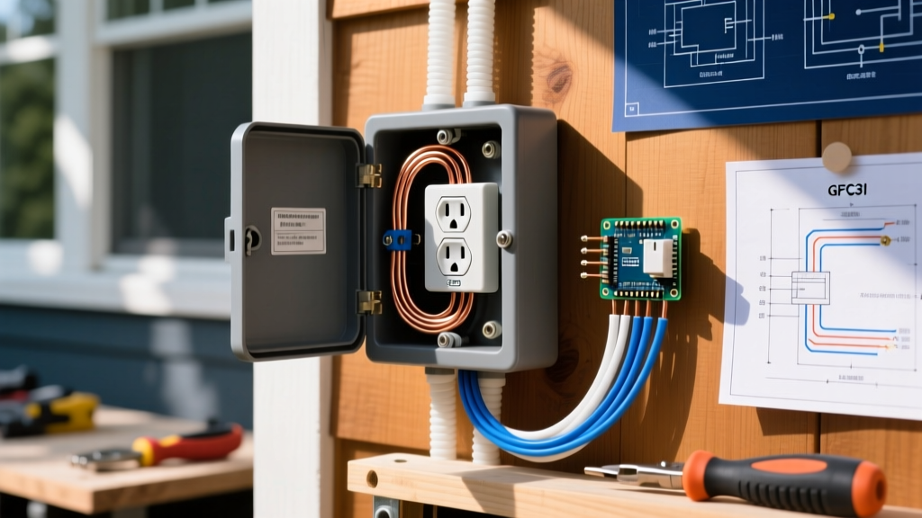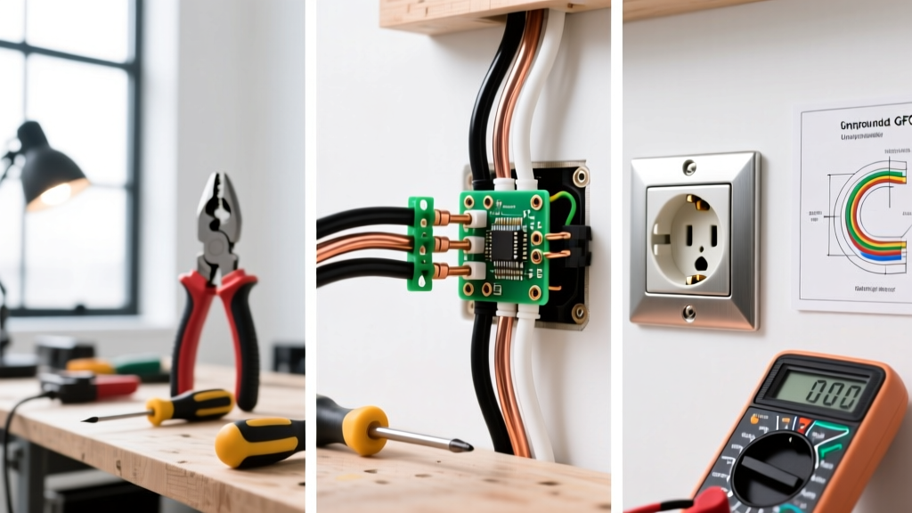

The Reality of Installing an Electric Outlet in Modern Homes
When installing an electric outlet, the "one-size-fits-all" approach is a fast track to tripped breakers, failed inspections, or severe fire hazards. As of 2026, the National Electrical Code (NEC) enforces stricter Arc-Fault (AFCI) and Ground-Fault (GFCI) mandates, and the proliferation of high-draw smart home devices means circuit capacity is at a premium. Whether you are adding a new receptacle to a bedroom wall or upgrading a kitchen backsplash, understanding the specific wiring scenario is critical.
Below, we break down three of the most common residential wiring scenarios, providing exact product recommendations, NEC code references, and step-by-step procedures to ensure your installation is safe, legal, and built to last.
Scenario 1: Daisy-Chaining a Standard Duplex Receptacle (Bedrooms & Living Areas)
The most frequent scenario when installing an electric outlet is adding a new 15-amp or 20-amp standard duplex receptacle to an existing circuit. This is common when mounting a TV or adding a home office workstation. The critical mistake DIYers make here is using the receptacle's side terminals to pass power to downstream outlets (daisy-chaining through the device). If that receptacle fails or a wire backs out, every outlet downstream loses power.
The Expert Method: Pigtailing with Lever Nuts
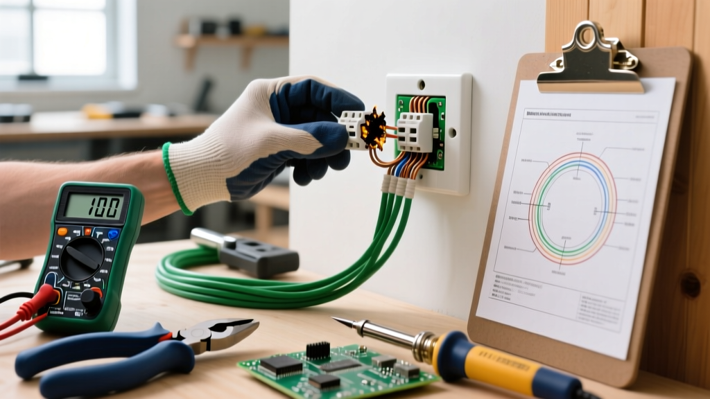
Instead of daisy-chaining through the device, use a pigtail. This involves connecting the incoming line wires, the outgoing load wires, and a short 6-inch "pigtail" wire together, then attaching only the pigtail to the receptacle.
- Wire Prep: Use Klein Tools 11063W wire strippers to strip exactly 5/8-inch of insulation from 14 AWG (for 15A circuits) or 12 AWG (for 20A circuits) solid copper wire.
- Connectors: Ditch the traditional twist-on wire nuts. Use Wago 221 Series Lever Nuts (specifically the 3-port or 5-port models). They provide a verified, gas-tight connection, eliminate the risk of under-torqueing, and allow for easy circuit modifications later.
- Receptacle Choice: For 15A circuits, the Leviton T5252-W (Tamper-Resistant) is an industry standard. For 20A circuits, use the Leviton R52-05352-W. Note: You can install a 15A receptacle on a 20A circuit if there are multiple receptacles on the circuit, per NEC 210.21(B)(3), but a 20A receptacle requires a 20A circuit.
Pro Tip: Always wrap the terminal screws clockwise. When you tighten the screw, the loop closes rather than spreading open. For ultimate code compliance in commercial or high-end residential builds, use a torque screwdriver set to the manufacturer's specification (typically 14 in-lbs for standard receptacles) to prevent cold solder joints or crushed wire strands.
Scenario 2: Upgrading a 2-Prong Ungrounded Outlet to a 3-Prong GFCI
Millions of homes built before the 1960s feature 2-prong, ungrounded receptacles. Homeowners often ask if they can simply swap these for modern 3-prong outlets. Legally and safely, you cannot install a standard grounded receptacle on an ungrounded circuit. However, there is a highly specific, NEC-compliant workaround when installing an electric outlet in this scenario.
NEC Article 406.4(D)(2): The GFCI Exception
The NEC allows you to replace a 2-prong ungrounded receptacle with a 3-prong Ground-Fault Circuit Interrupter (GFCI), provided you apply a specific warning label. The GFCI protects the user from lethal shock by monitoring current imbalance, which does not require an equipment grounding conductor to function.
- Power Down & Verify: Turn off the breaker and verify zero voltage using a non-contact tester and a multimeter (e.g., Fluke 117).
- Identify Wires: You will only have a hot (black) and a neutral (white). There will be no bare copper or green ground wire.
- Wire the GFCI: Connect the hot wire to the brass LINE terminal and the neutral to the silver LINE terminal on the GFCI. Do not use the LOAD terminals unless you are protecting downstream ungrounded outlets (which also require the warning sticker).
- Ground Screw: Leave the green ground screw on the GFCI empty. Do not bootleg a ground by connecting it to the neutral or the metal box.
- Apply the Sticker: The GFCI packaging includes a "No Equipment Ground" sticker. You must apply this to the faceplate. Without it, the installation fails inspection.
Recommended Product: The Eaton GFTR20W 20-Amp GFCI is highly regarded for its robust internal solenoid and resistance to nuisance tripping, which is vital in older homes with slightly noisy electrical panels.
Scenario 3: Wiring a 20A GFCI in a Wet Location (Kitchen & Bathroom)
Kitchens, bathrooms, garages, and outdoor patios require GFCI protection. When installing an electric outlet in these zones, the most common failure point is miswiring the LINE and LOAD terminals, resulting in downstream outlets that lack shock protection or a GFCI that refuses to reset.
Decoding LINE vs. LOAD
A GFCI receptacle has two sets of terminals: LINE (power coming from the panel) and LOAD (power going to downstream outlets). The internal ground-fault sensor sits between these two sets. If you wire the incoming power to the LOAD terminals, the GFCI will not protect itself, and the "Test" button will not trip the device.
Step-by-Step Wet Location Wiring
- Identify the Feed: Before disconnecting the old wires, use a voltage tester to identify which pair of wires is hot. This is your LINE.
- Terminate the LINE: Connect the incoming hot and neutral to the LINE terminals. Use the internal strip gauge on the back of the Leviton GFTNL-W (SmartlockPro 20A) to ensure exact wire stripping.
- Terminate the LOAD: Connect the downstream hot and neutral wires to the LOAD terminals. This extends GFCI protection to the rest of the circuit.
- Weather-Resistant (WR) Rating: If the outlet is outdoors or in a highly damp area, NEC 406.9(A) requires a WR-rated receptacle and an in-use weatherproof bubble cover. WR receptacles feature UV-resistant plastics and nickel-plated brass terminal screws to resist corrosion.
Quick-Reference Matrix: Breaker, Wire, and Receptacle Matching
Mismatching wire gauges and breaker sizes is a leading cause of electrical fires. Use this matrix to ensure your installation meets 2026 safety standards.
| Circuit Breaker Size | Minimum Copper Wire Gauge (THHN/NM-B) | Maximum Single Receptacle Rating | Max Continuous Load (80% Rule) |
|---|---|---|---|
| 15 Amp | 14 AWG | 15 Amp | 12 Amps (1,440W at 120V) |
| 20 Amp | 12 AWG | 20 Amp | 16 Amps (1,920W at 120V) |
| 30 Amp | 10 AWG | 30 Amp (Specialty/TT-30) | 24 Amps (2,880W at 120V) |
Troubleshooting Common Installation Failures
Even experienced DIYers run into issues when installing an electric outlet. Here is how to diagnose the three most common post-installation failures:
1. The GFCI Will Not Reset
Cause: Reversed Line and Load wiring, or an upstream ground fault on the circuit.
Fix: Pull the receptacle out, verify the incoming power is on the LINE terminals using a multimeter. If the wiring is correct, check for a downstream fault by disconnecting the LOAD wires and capping them. If the GFCI resets, the fault is in the downstream wiring.
2. Receptacle Tester Shows "Open Neutral"
Cause: The white neutral wire has backed out of the wire nut or the terminal screw.
Fix: Turn off the power, pull the device, and tug-test every neutral wire. If using side-wiring (back-stabbing), switch to screw-terminal wiring or use the side-clamp plates found on higher-end spec-grade receptacles, which grip the wire much more securely.
3. Nuisance Tripping on AFCI/GFCI Breakers
Cause: Shared neutrals (multi-wire branch circuits) improperly wired, or long cable runs causing capacitive leakage.
Fix: Ensure that the hot and neutral for the specific circuit are kept entirely separate from other circuits in the junction box. If using a MWBC (Multi-Wire Branch Circuit), you must use a 2-pole AFCI/GFCI breaker, not individual receptacle-level protection.
Safety and Code Compliance Resources
Electrical work carries inherent risks. Always consult your local Authority Having Jurisdiction (AHJ), as local amendments may supersede national codes. For comprehensive safety guidelines and the latest code adoptions, refer to the National Fire Protection Association (NFPA) NEC resources. Additionally, the U.S. Consumer Product Safety Commission (CPSC) Home Electrical Safety Center provides vital data on preventing electrical fires and shocks in residential settings.
By understanding the nuances of pigtailing, ungrounded GFCI exceptions, and LINE/LOAD configurations, you ensure that installing an electric outlet enhances your home's functionality without compromising its safety.