
The Anatomy of a Code-Compliant Electric Generator Outlet Setup
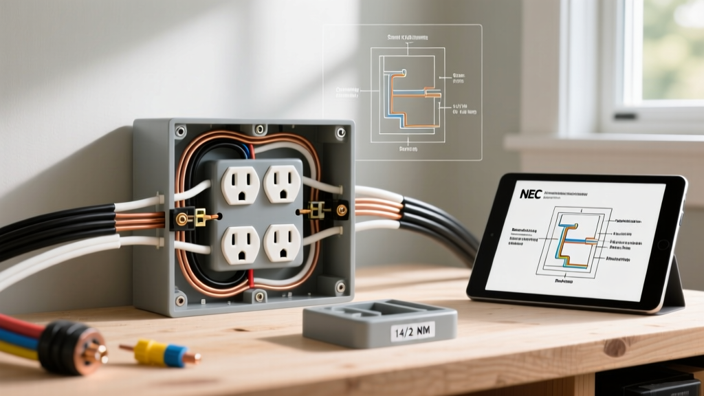
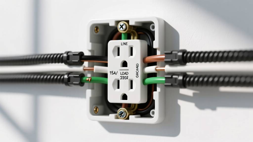
When homeowners refer to an 'electric generator outlet,' they are typically describing the exterior receptacle where the generator connects to the home's electrical system. In professional electrical terminology, this is an inlet box containing a male-flanged receptacle (like a NEMA L14-30P configuration acting as the inlet), while the generator's twist-lock cord features the female connector. Installing this system is not merely about drilling a hole and mounting a box; it requires strict adherence to NEC Article 702 (Optional Standby Systems) to prevent backfeeding, which can be fatal to utility lineworkers.
As of the 2026 NEC adoption cycles, local inspectors are heavily scrutinizing neutral-to-ground bonding, torque specifications on terminal lugs, and the physical interlocking mechanisms that prevent the main utility breaker and the generator backfeed breaker from being closed simultaneously. This guide details the exact tools, materials, and hardware required to execute a professional-grade electric generator outlet and inlet box installation.
NEMA Receptacle Configurations: Sizing Your Inlet
Selecting the correct NEMA configuration for your electric generator outlet depends entirely on your generator's running wattage and the amperage rating of its main circuit breaker. Below is the definitive matrix for residential and light-commercial standby setups.
| NEMA Config | Amps / Volts | Wire Gauge (Copper) | Max Wattage | Typical Generator Size |
|---|---|---|---|---|
| L5-30R | 30A / 125V | 10 AWG (3-Wire) | 3,750W | Small Inverter (3500W-4500W) |
| L14-30R | 30A / 125/250V | 10 AWG (4-Wire) | 7,500W | Mid-Size Portable (7500W-8500W) |
| L14-50R | 50A / 125/250V | 6 AWG (4-Wire) | 12,500W | Large Portable (10,000W-12,500W) |
| 14-50R | 50A / 125/250V | 6 AWG (4-Wire) | 12,500W | Whole-Home Standby (Straight Blade) |
Pro-Tip: The L14-30R is the undisputed standard for portable residential generators in the 7,500W to 8,500W class. Always opt for a 4-wire setup (two hots, one neutral, one ground) to support both 240V well pumps and 120V lighting circuits simultaneously.
Essential Tools for Inlet Box and Transfer Switch Wiring
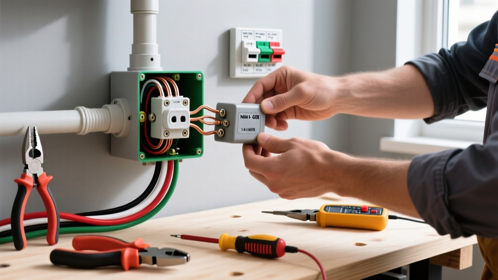
Roughing in an electric generator outlet and connecting it to a manual transfer switch (MTS) or interlock kit demands precision. Standard handyman tools will lead to failed inspections and potential thermal arcing.
1. Precision Wire Stripping and Ferrule Crimping
- Wire Strippers: The Klein Tools 11055 (10-20 AWG) and Klein 11057 (for larger gauge solid/stranded) are mandatory for clean cuts without nicking the copper, which reduces ampacity.
- Ferrule Crimper: When terminating stranded 10 AWG or 6 AWG THHN wire into the screw-terminals of a Reliance Controls inlet box, use a Knipex 97 53 14 ferrule crimper with insulated twin ferrules. This prevents 'strand splaying' where a single rogue copper strand escapes the terminal block, creating a high-resistance short-circuit point.
2. Torque Control and Fastening
The 2023 and 2026 NEC editions (specifically 110.14(D)) mandate that terminations be torqued to the manufacturer's specifications. Hand-tightening is no longer acceptable.
- Torque Screwdriver: A calibrated Wera VDE 0300 or Milwaukee 2101-20 torque driver. Most 30A NEMA L14-30R inlet box terminals require exactly 35 to 45 inch-pounds of torque. Over-torquing strips the brass threads; under-torquing causes resistive heating and eventual melting of the inlet box housing.
- Nut Drivers: Klein Tools 32308 multi-bit nut driver for securing the 3/4-inch EMT conduit locknuts and inlet box flange screws.
Material Bill of Quantities (BOM) for a 30-Amp System
For a standard 7,500W portable generator setup, your material list must include UV-rated, weatherproof exterior components and properly rated interior switching mechanisms.
Exterior Inlet Box
The Reliance Controls PB30 (30-Amp, 125/250V) is the industry benchmark, typically retailing between $85 and $115 in 2026. It features a NEMA 3R rating, a hinged weatherproof flapper cover, and knockouts on the bottom and back for flexible conduit routing. Avoid unbranded, plastic-molded inlet boxes from overseas marketplaces; they frequently lack UL listing marks and use inferior brass alloys that oxidize rapidly in humid climates.
Interior Switching: MTS vs. Interlock Kit
You have two code-compliant methods to route power from the electric generator outlet to your panel:
- Manual Transfer Switch (MTS): A sub-panel like the Generac 6294 (10-circuit, 30A, $350-$450). This isolates specific circuits. It requires running individual 12 AWG or 10 AWG THHN wires from the MTS to the circuits you want to back up.
- Generator Interlock Kit: A mechanical steel slide plate (e.g., Siemens ECSBPK01 or Eaton CHGENPKG2, $60-$90) installed on your existing main panel. This allows you to backfeed the entire panel (up to the inlet's 30A limit) using a single 2-pole 30A breaker. This is often preferred in 2026 for its lower material cost and ability to manage loads dynamically via smart panel monitoring.
Wire and Conduit
- Conductors: Four strands of 10 AWG THHN/THWN-2 (Black, Red, White, Green). Expect to pay $0.85 to $1.20 per foot per strand in the current copper market.
- Conduit: 3/4-inch Schedule 40 PVC for exterior runs, or 3/4-inch EMT (Electrical Metallic Tubing) for interior exposed garage walls.
- Pulling Lubricant: Ideal 75-0001 Yellow 7515 wire pulling lube. Never pull dry THHN through 90-degree conduit sweeps, as the friction can micro-tear the insulation, leading to ground faults.
Critical Edge Cases and Failure Modes
Even with the right tools, improper configuration of the electric generator outlet system leads to catastrophic failures. Be aware of these specific edge cases:
The Neutral Bonding Trap
This is the most common reason for failed inspections and tripped GFCI/AFCI breakers. By NEC code, the neutral and ground must be bonded at exactly one point in the system (the main utility service disconnect). If your portable generator has a bonded neutral (common in older or contractor-grade models) AND your home's main panel has a bonded neutral, you have created a parallel neutral path. When the generator runs, return current will flow over the equipment grounding conductors, tripping AFCI/GFCI breakers and energizing the generator's metal frame.
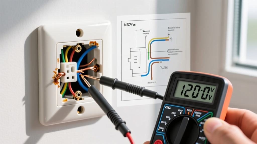
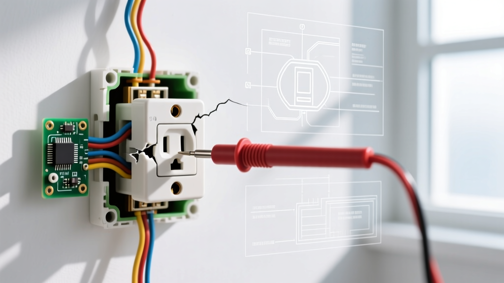
The Fix: Use a multimeter to check continuity between the neutral and ground prongs on the generator's L14-30R outlet. If there is continuity, you must either convert the generator to a 'floating neutral' (following the manufacturer's exact modification kit instructions) or install a switched neutral relay in your transfer setup.
Thermal Arcing and Inlet Box Melting
Failure to use ferrules on stranded wire, or failing to torque the inlet box lugs to 45 in-lbs, results in a high-resistance connection. Under a sustained 25-amp load (like running an HVAC compressor and well pump simultaneously), a loose connection will generate immense heat. We frequently see melted PB30 inlet boxes where the plastic housing deforms, fusing the weather cover shut. Always perform a thermal scan with an IR thermometer or FLIR camera after the first 30 minutes of full-load generator operation.
Authoritative Safety and Code References
Before energizing your electric generator outlet, consult the latest safety standards. Backfeeding without a mechanical interlock or transfer switch is illegal and deadly. Always refer to:
- NFPA 70 National Electrical Code (NEC) - Specifically Article 445 (Generators) and Article 702 (Optional Standby Systems) for bonding and disconnect rules.
- FEMA Generator Safety Guidelines - Crucial protocols for carbon monoxide placement, clearance distances from eaves, and wet-weather operation.
- CPSC Portable Generator Safety - Data on backfeed electrocution hazards and mandatory transfer switch utilization.
By utilizing precision torque tools, UL-listed inlet hardware, and strictly adhering to neutral bonding protocols, your electric generator outlet installation will provide reliable, safe, and code-compliant backup power for decades.