
Upgrading to a NEMA L14-30P: The 2026 Standard for 30-Amp Power
When managing high-draw portable power, the NEMA L14-30 plug is the undisputed workhorse for residential and light-commercial generator setups. Whether you are upgrading from a standard 14-30 dryer receptacle, replacing a heat-damaged twist-lock plug, or installing a new manual transfer switch, understanding the exact wiring diagram for L14 30 plug configurations is critical. A flawed termination on a 30-amp, 250-volt circuit does not just trip breakers; it creates severe fire hazards and equipment destruction risks.
As of 2026, the market has seen a surge in smart transfer switches and dual-fuel inverter generators that rely heavily on the L14-30R receptacle. Consequently, the male plug (L14-30P) on your generator cord endures immense mechanical and thermal stress. This comprehensive upgrade and replacement guide provides the exact pinout data, torque specifications, and failure-mode analysis required to execute a code-compliant termination.
Decoding the Wiring Diagram for L14 30 Plug Configurations
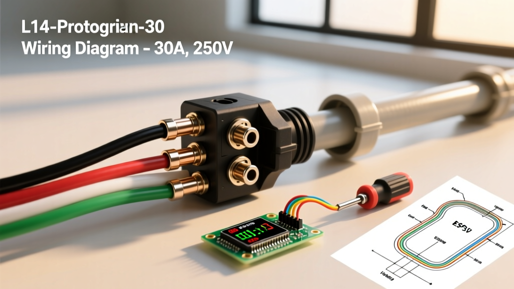
The NEMA L14-30P is a 4-wire, single-phase, 125/250-volt locking plug. The 'L' designates the twist-lock mechanism, which prevents accidental disconnects under load—a vital safety feature outlined by OSHA Electrical Safety Guidelines for temporary power feeds. Before stripping any wire, you must understand the terminal designations stamped inside the plug housing.
The Four-Pin Anatomy
- X (Hot 1): Carries 125V from the first phase. Typically terminated with a Black wire.
- Y (Hot 2): Carries 125V from the second phase. Typically terminated with a Red wire. The potential difference between X and Y is 250V.
- W (Neutral): The grounded current-carrying conductor. Terminated with a White wire. This is critical for balancing 120V loads across the two hot legs.
- G (Ground): The equipment grounding conductor (EGC). Terminated with a Green or Bare Copper wire. This provides the fault-current path back to the source.
Expert Warning: Never swap the Neutral (W) and Ground (G) terminals. While a 240V-only load might appear to function if wired incorrectly, any 120V branch circuit downstream will energize the grounding system, creating a lethal shock hazard and violating NEC Article 250.
Wire Gauge, Cable Types, and Voltage Drop Matrix
Selecting the correct SOOW or STOW flexible cord is just as important as the termination itself. Undersized cables will overheat, melting the plug housing from the inside out. Below is the 2026 specification matrix for L14-30 cord sets based on run length.
| Cable Type | Wire Gauge (AWG) | Max Run Length | Voltage Drop at 30A | Estimated Cost per Foot (2026) |
|---|---|---|---|---|
| SOOW 10/4 | 10 AWG | 50 Feet | ~3.2% | $3.80 - $4.50 |
| SOOW 8/4 | 8 AWG | 100 Feet | ~2.5% | $5.50 - $6.75 |
| SOOW 6/4 | 6 AWG | 150+ Feet | ~1.8% | $8.20 - $9.50 |
Note: Always calculate voltage drop based on the continuous 120V leg load. The National Electrical Code (NEC) recommends keeping voltage drop under 3% for branch circuits and feeders combined. Refer to the National Electrical Code (NEC) for exact derating tables.
Step-by-Step L14-30P Replacement Procedure
If your existing plug shows signs of thermal discoloration, cracked housing, or loose prongs, immediate replacement is required. Premium replacement plugs like the Hubbell 2621 or Leviton 2621 typically cost between $22 and $35 and feature rugged nylon housings with brass terminal lugs.
Step 1: Safe Disassembly and Cable Prep
Ensure the generator is off and the transfer switch is isolated. Unscrew the cord grip and terminal housing. If reusing the existing cable, cut back at least 2 inches past the previous termination point to expose fresh, un-oxidized copper. Strip the outer jacket back exactly 2.5 inches. Strip the individual insulated conductors to exactly 0.75 inches (3/4 inch). Do not nick the copper strands, as this creates localized hot spots under load.
Step 2: Conductor Dressing and Termination
Twist the exposed copper strands tightly clockwise. This ensures the strands wrap around the terminal screw in the same direction the screw tightens, preventing splaying. Insert the wires into their respective terminals (X, Y, W, G).
Step 3: Precision Torque Application
This is where most DIYers fail. Hand-tightening is insufficient for a 30-amp circuit. Thermal cycling will loosen undertorqued screws, leading to arcing. Use a calibrated torque screwdriver set to 15 to 20 inch-pounds (verify the specific stamp on your plug's interior). Tighten the terminal screws firmly. Give each wire a firm tug to ensure it is mechanically locked.
Step 4: Strain Relief and Reassembly
The cord grip (strain relief) must clamp down exclusively on the thick outer rubber jacket of the SOOW cable, never on the inner insulated wires. If the grip compresses the inner wires, it will crush the insulation and cause a short circuit. Reassemble the housing, ensuring the internal ribs align to separate the terminal lugs, preventing phase-to-phase contact.
Common Failure Modes and Troubleshooting
Even with a perfect wiring diagram for L14 30 plug execution, environmental factors and load imbalances can cause issues. Recognizing these edge cases separates novices from experts.
1. Melted Neutral Lug (The Imbalance Problem)
Symptom: The X and Y terminals look pristine, but the W (Neutral) terminal shows severe heat discoloration or melted nylon.
Root Cause: In a split-phase 120/240V system, the neutral only carries the imbalance between the two hot legs. However, if your transfer switch or generator has a heavily skewed 120V load (e.g., pulling 25A on Hot 1 and 2A on Hot 2), the neutral is forced to carry 23A continuously. Combined with a slightly loose terminal, this generates massive resistive heat.
Fix: Balance your 120V loads across both hot legs at the transfer switch panel. Retorque the neutral lug.
2. Intermittent Power Loss Under Vibration
Symptom: Generator runs smoothly, but power drops out when the engine RPM surges or the cord is bumped.
Root Cause: Splayed copper strands inside the terminal lug or a failing internal cord grip allowing the cable to pull away from the lugs.
Fix: Replace the plug. Ensure the cord grip is tightened with channel-lock pliers, not just by hand, to bite into the SOOW jacket.
3. Ground Pin Shearing
Symptom: The elongated ground pin (G) breaks off inside the receptacle.
Root Cause: Dropping the plug onto concrete or forcing it into a misaligned L14-30R receptacle without twisting first.
Fix: Never attempt to glue or solder the pin back on. The mechanical integrity is compromised. Replace the plug head immediately.
Code Compliance and Generator Safety
When upgrading your L14-30 setup, strict adherence to electrical codes is non-negotiable. According to FEMA and Ready.gov generator safety protocols, portable generators must never be backfed into a home's main panel without a properly installed, code-compliant transfer switch. The L14-30 plug is designed to connect to a transfer switch inlet box (e.g., Reliance Controls PB30), which physically isolates the generator from the utility grid.
Furthermore, NEC Article 406 dictates that all 125/250V receptacles and locking plugs must be rated for the specific amperage and voltage of the circuit. Using a 30-amp plug on a 50-amp generator outlet via an adapter is a severe code violation that bypasses the generator's internal overcurrent protection.
Final Thoughts on L14-30 Upgrades
Mastering the wiring diagram for L14 30 plug terminations ensures your backup power system is reliable, safe, and ready for severe weather events. By utilizing 10 AWG or 8 AWG SOOW cable, applying exact torque specifications, and understanding the thermal dynamics of split-phase neutral loads, you guarantee a professional-grade connection. Always inspect your twist-lock plugs annually for signs of UV degradation, thermal stress, and pin wear to maintain peak system integrity.