
Mastering the Basics: How to Install an Electrical Outlet with Professional Precision
Understanding how to install an electrical outlet goes far beyond simply connecting wires to a plastic faceplate. In 2026, modern electrical codes demand rigorous adherence to torque specifications, tamper-resistant mandates, and precise box-fill calculations. Whether you are upgrading a damaged 15-amp receptacle in a living room or wiring a new 20-amp kitchen circuit, the margin for error is zero. A poorly terminated neutral wire can cause thermal runaway, leading to melted insulation and structural fires.
This comprehensive tool and material guide bridges the gap between amateur guesswork and journeyman-level execution. We will dissect the exact diagnostic instruments, wire preparation tools, and code-compliant materials required to execute a flawless, safe, and durable outlet installation.
The Professional-Grade Toolkit for Outlet Installation
Before cutting into any drywall or stripping a single wire, you must assemble a toolkit designed for safety and precision. Relying on dull, multi-purpose tools is a primary cause of nicked conductors and loose terminations.
1. Diagnostic and Safety Instruments
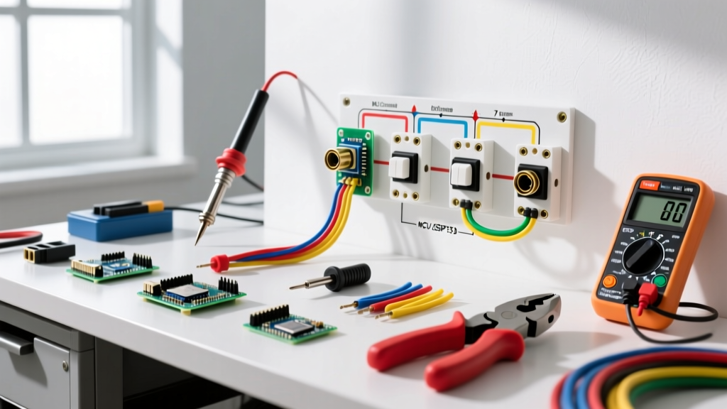
- Non-Contact Voltage Tester (NCVT): The Klein Tools NCVT-2 (approx. $30) is the industry standard. It detects voltage from 12V to 1000V AC. Pro Tip: Always test the NCVT on a known live source before and after testing your target circuit to verify the tool's battery and sensor integrity.
- Receptacle Tester: The Gardner Bender GFI-3501 (approx. $15) features a built-in GFCI trip button and LED matrix to instantly identify reverse polarity, open grounds, and hot/neutral swaps.
- Insulated Screwdrivers: Invest in VDE-certified 1000V insulated drivers, such as the Wiha 32091 PicoFinish set. Standard hardware store screwdrivers offer zero dielectric protection if a concealed live wire is accidentally bridged.
2. Wire Preparation and Termination Tools
- Precision Wire Strippers: The Klein Tools 11063W Katapult is engineered specifically for 14-12 AWG solid copper wire. Unlike combination pliers that crush the copper core, the Katapult's calibrated shear removes the PVC jacket without scoring the metal, preserving the wire's tensile strength and conductivity.
- Calibrated Torque Screwdriver: Under NEC 110.14(D), electrical terminations must be tightened to the manufacturer's specified torque. For standard 15A and 20A receptacles, this is typically 14 in-lbs. A tool like the Klein Tools 70101 (approx. $150) prevents under-tightening (which causes arcing) and over-tightening (which strips the brass terminal threads).
- Side-Cutting Pliers (Lineman's Pliers): The Klein Tools 200048EINS insulated linemans are essential for gripping, twisting wire nuts, and snipping 12 AWG Romex cleanly.
Material Selection Matrix: 15A vs. 20A Configurations
Selecting the correct materials is dictated by the circuit breaker size and the physical location of the outlet. The National Electrical Code (NEC) strictly governs these pairings. For detailed code references, consult the National Fire Protection Association (NFPA) NEC guidelines.
| Component | 15-Amp Circuit (Bedrooms, Living Rooms) | 20-Amp Circuit (Kitchens, Bathrooms, Garages) |
|---|---|---|
| Circuit Breaker | 15A Single-Pole (e.g., Eaton BR115) | 20A Single-Pole (e.g., Square D HOM120) |
| Wire Gauge | 14 AWG Solid Copper (14/2 NM-B) | 12 AWG Solid Copper (12/2 NM-B) |
| Receptacle Type | 15A Tamper-Resistant (TR) Duplex | 20A TR Duplex OR 15A TR Duplex |
| Box Volume (Min) | 14 cubic inches (for 1 cable entering) | 18 cubic inches (for 12 AWG wire fill) |
| Device Model | Leviton T5320-W (Approx. $3.50) | Leviton T5262-W (Approx. $5.00) |
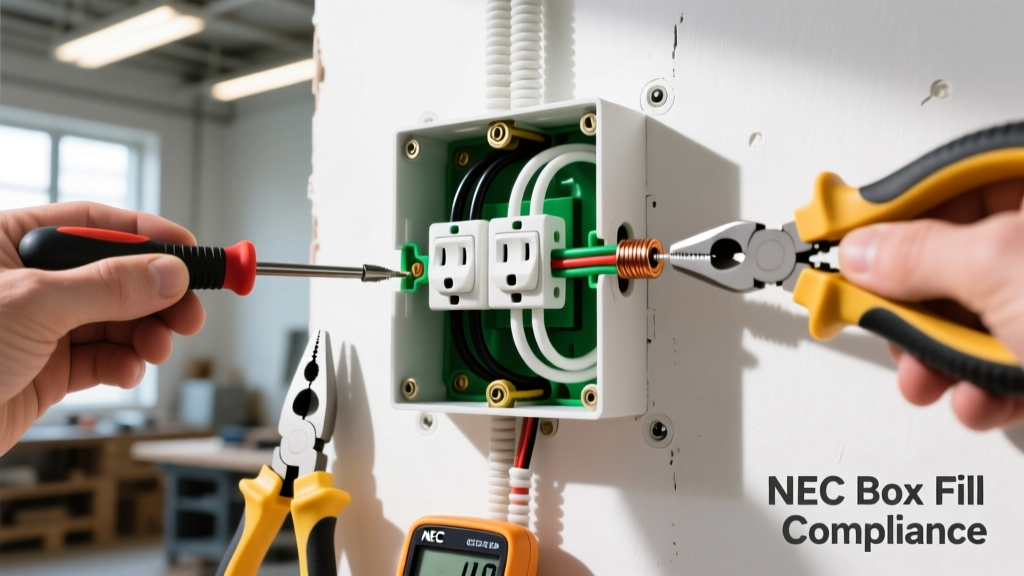
NEC Box Fill Warning: Never cram wires into an undersized electrical box. According to NEC 314.16(B), each 12 AWG conductor counts as 2.25 cubic inches of fill, while 14 AWG counts as 2.0 cubic inches. The internal clamp, the device (outlet), and grounding wires also consume volume. Always calculate total fill before selecting your old-work or new-work box.
Step-by-Step Installation: Applying the Right Tools
With your materials staged and the circuit breaker locked out at the main panel, follow this precision workflow.
Phase 1: Verification and Jacket Removal
- Verify Dead Circuit: Insert the Klein NCVT-2 into the top and bottom slots of the existing outlet. Confirm zero voltage indication.
- Sheath the Romex: Use a cable ripper (Romex slitter) to slice the outer PVC jacket exactly 8 inches from the entry point of the electrical box. Never use a utility knife to score the jacket, as this inevitably nicks the internal ground or neutral wires, creating a high-resistance fault point.
- Fold the Ground: Leave the bare copper ground wire slightly longer than the insulated conductors. This ensures that if the cable is accidentally pulled, the ground connection breaks last, maintaining safety.
Phase 2: Precision Stripping and the Shepherd's Hook
The geometry of your wire termination dictates the longevity of the connection.
- Strip Length: Look at the back of the Leviton receptacle. You will see a 'strip gauge' molded into the plastic yoke. For most modern devices, this requires exactly 5/8 inch to 3/4 inch of exposed copper. Use the Klein Katapult to strip to this exact line.
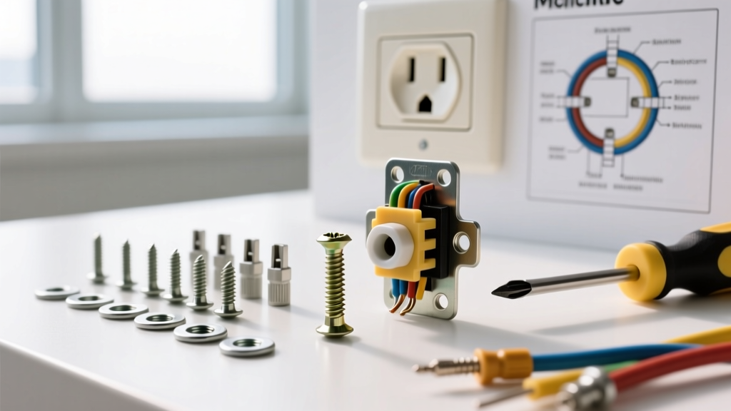
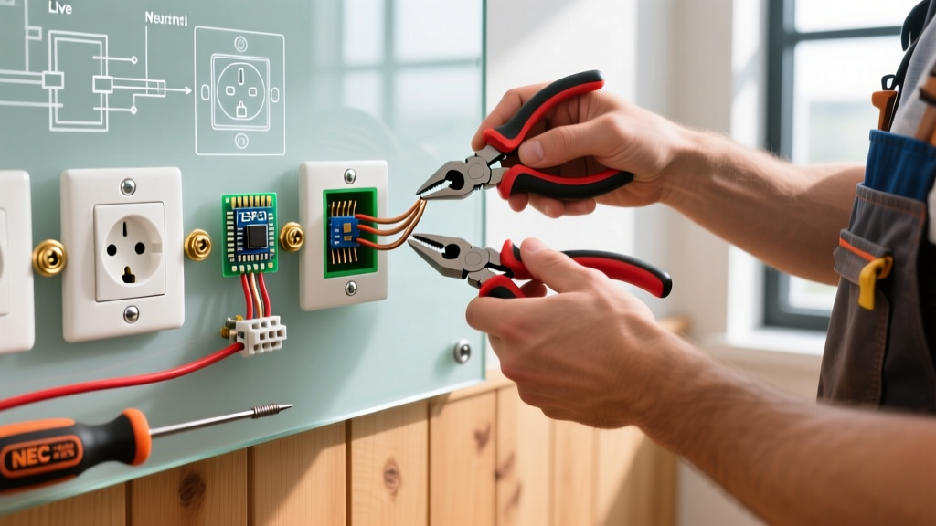
- Forming the Loop: Using the needle-nose section of your lineman's pliers, bend the exposed copper into a tight 'J-hook' or shepherd's hook. The loop must be perfectly circular so it sits flush against the terminal washer.
- Clockwise Orientation: Always hook the wire around the terminal screw in a clockwise direction. As you tighten the screw (clockwise), the loop is pulled tighter around the shaft. A counter-clockwise hook will be pushed out from under the screw head as torque is applied.
Phase 3: Torque-Specified Termination
This is where amateur installations fail. Hand-tightening is no longer acceptable under modern electrical inspection standards.
- Seat the clockwise J-hook under the brass (hot) and silver (neutral) terminal plates.
- Set your calibrated torque screwdriver to the receptacle manufacturer's specification (usually 14 in-lbs for standard residential duplexes).
- Drive the screw until the torque driver clicks. This ensures optimal surface contact area, minimizing electrical resistance and preventing the terminal from loosening due to thermal expansion and contraction cycles over the years.
- Connect the bare ground wire to the green grounding screw using the same torque protocol.
Critical Failure Modes and How to Avoid Them
Understanding why outlets fail is just as important as knowing how to install them. Avoid these common, hazardous pitfalls:
1. The 'Backstab' Push-In Connection
Many cheap receptacles feature quick-wire push-in holes on the back. Never use these. They rely on a tiny internal spring-steel wedge that grips the wire. Over time, the high current draw (like a space heater or vacuum) causes thermal cycling, which weakens the spring. The wire loosens, arcs, and melts the plastic housing. Always use the side-terminal screw plates or the screw-clamp 'back-wire' plates found on commercial-grade (spec-grade) receptacles.
2. Reverse Polarity and Bootleg Grounds
Reverse polarity (hot and neutral swapped) means the internal switch of a plugged-in appliance won't actually disconnect the dangerous voltage, leaving the device 'live' even when turned off. A 'bootleg ground' occurs when a jumper wire is illegally installed between the neutral and ground screws to trick a home inspector's 3-light tester. This creates a severe shock hazard if the neutral wire ever breaks upstream. Always verify your wiring topology with a multimeter, not just a cheap plug-in tester. For more on residential electrical hazards, review the Consumer Product Safety Commission (CPSC) electrical safety guidelines.
3. Pigtailing vs. Daisy-Chaining
When an outlet is in the middle of a circuit run (power coming in, power going out), do not connect two hot wires and two neutral wires directly to a single receptacle's side terminals. If the receptacle is ever removed, the downstream circuit dies. Instead, use Wago 221 lever-nuts or wire nuts to 'pigtail' the wires. Connect the incoming and outgoing wires together with a third, short 6-inch wire (the pigtail) that terminates at the receptacle. This ensures continuous circuit integrity regardless of the device's presence.
2026 Cost Breakdown: Tool Investment vs. Material Costs
Investing in the right tools pays dividends in safety and time. Here is a realistic look at the capital required for a professional-grade DIY outlet installation.
| Category | Item | Estimated 2026 Cost | Frequency of Use |
|---|---|---|---|
| Diagnostic | Klein NCVT-2 & Receptacle Tester | $45.00 | Every Project |
| Preparation | Klein Katapult Strippers & Linemans | $75.00 | Every Project |
| Termination | Klein Torque Screwdriver (14 in-lbs) | $150.00 | Every Project |
| Materials | Leviton TR Receptacle & Carlon Box | $6.00 | Per Outlet |
| Materials | Wago 221 Lever-Nuts (Pigtailing) | $8.00 / pack | As Needed |
Final Safety and Compliance Directives
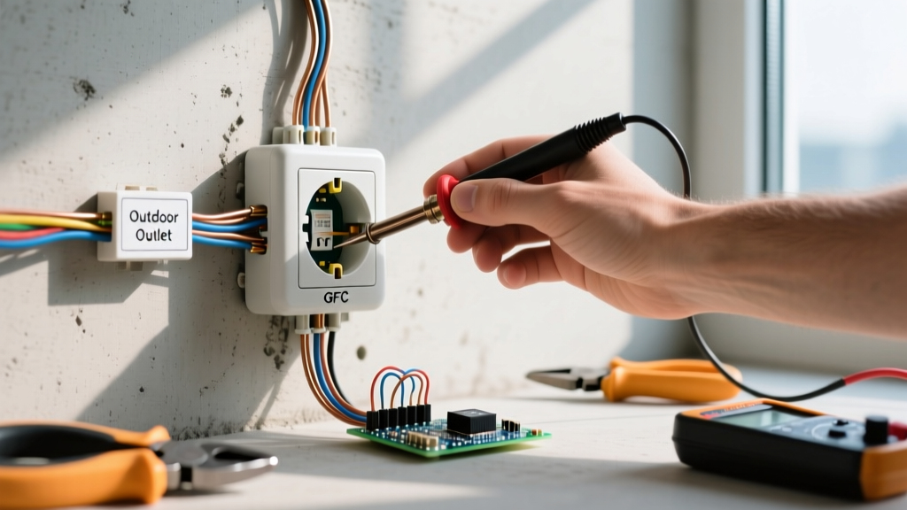
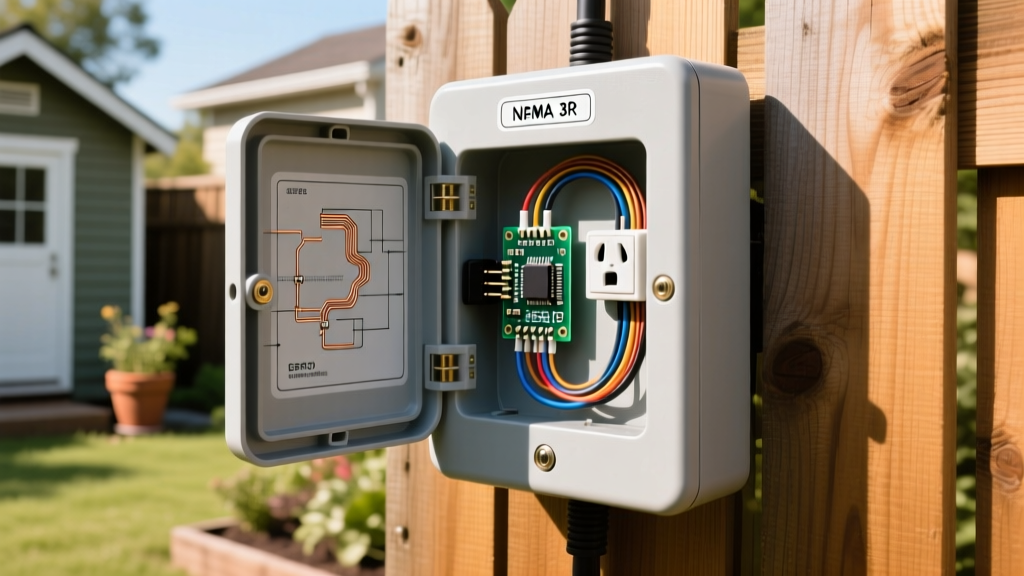
Knowing how to install an electrical outlet is a highly rewarding DIY skill, but it carries inherent risks. Always ensure your local jurisdiction allows homeowner electrical work; some municipalities require a licensed electrician for any new wiring or modifications. Furthermore, any outlet installed in wet locations (bathrooms, kitchens, garages, exteriors) must be GFCI (Ground Fault Circuit Interrupter) protected, and bedrooms/living areas generally require AFCI (Arc Fault Circuit Interrupter) protection at the breaker panel, as mandated by the latest OSHA and NEC residential safety standards.
By utilizing calibrated torque tools, respecting box-fill volumes, and refusing to use backstab connections, your outlet installation will not only pass inspection but will provide decades of safe, reliable service without the threat of thermal degradation.