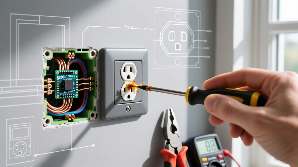

Core Principles of Outlet Wiring Reference
When installing electrical outlet devices in residential or commercial environments, understanding the underlying wiring diagrams is non-negotiable. A miswired receptacle doesn't just trip breakers; it creates severe shock hazards, fire risks, and equipment damage. This reference guide decodes the standard wiring topologies for the most common receptacles encountered in the field, updated for the 2026 National Electrical Code (NEC) adoption cycle.
Before interpreting any diagram, verify your cable type. Standard residential branch circuits utilize Non-Metallic (NM-B) sheathed cable, commonly known as Romex. For 15-amp circuits, 14 AWG copper is standard, while 20-amp circuits mandate 12 AWG copper. Always confirm the circuit is de-energized using a non-contact voltage tester like the Fluke 1AC-II VoltAlert before exposing any conductors.
⚠️ CRITICAL SAFETY WARNING: Never rely solely on a wall switch to de-energize a circuit. Always verify zero voltage at the receptacle terminals. According to the U.S. Consumer Product Safety Commission (CPSC), electrical receptacles are involved in thousands of residential fires annually, often stemming from loose connections or reversed polarity.
Standard 15A and 20A Duplex Receptacle Diagrams
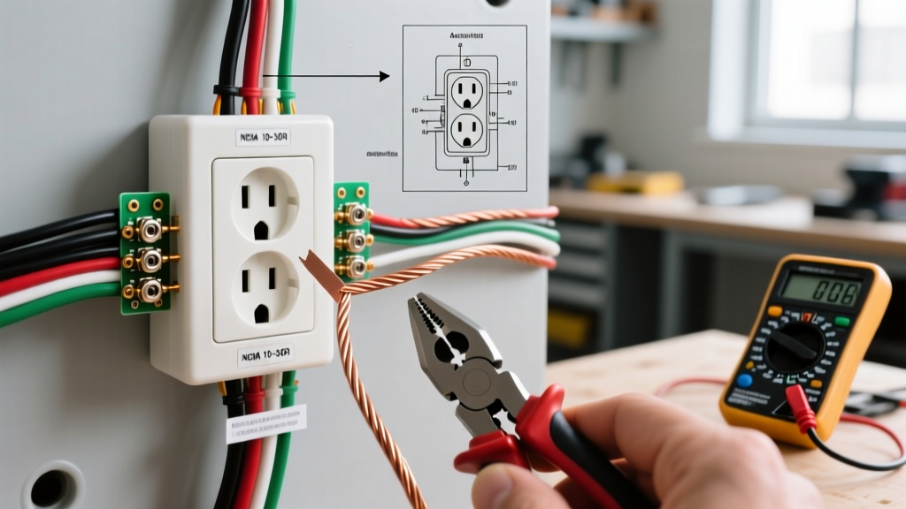
The standard NEMA 5-15R (15A) and NEMA 5-20R (20A) duplex receptacles are the backbone of household power. The wiring diagram for a standard end-of-run or mid-run receptacle relies on a simple color-to-terminal mapping.
| Wire Color | Function | Terminal Screw Color | Connection Point |
|---|---|---|---|
| Black (or Red/Blue) | Ungrounded (Hot) | Brass / Gold | Right Side (facing front) |
| White (or Gray) | Grounded (Neutral) | Silver | Left Side (facing front) |
| Bare Copper / Green | Equipment Ground | Green | Bottom / Center |
The Back-Wire Clamp vs. Push-In Debate
When installing electrical outlet devices, you will notice three connection methods on the back of modern receptacles like the Leviton T5262:
- Side Wiring (Looping): Wrapping the stripped wire clockwise around the terminal screw. Reliable, but time-consuming.
- Push-In (Stab) Connections: Inserting stripped wire into small holes that grip via a spring clip. Avoid these. They offer minimal surface area contact and are a leading cause of high-resistance heating and arcing over time.
- Back-Wire Clamps: Inserting the wire into a hole and tightening the screw to lower a solid brass clamp plate. This is the professional standard, offering the pull-out resistance of a screw terminal with the speed of a push-in.
GFCI Receptacle Wiring: Line vs. Load
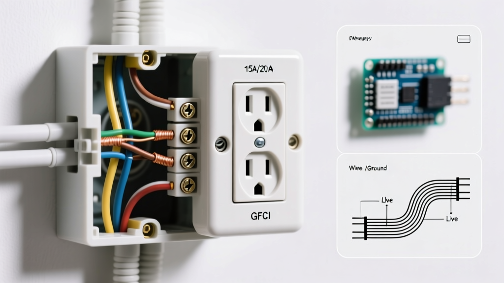
Ground Fault Circuit Interrupter (GFCI) receptacles, such as the Pass & Seymour 2095TR, are required by the National Fire Protection Association (NFPA) in all wet or damp locations, including kitchens, bathrooms, garages, and outdoor patios. The wiring diagram for a GFCI is distinctly different from a standard duplex because it features two sets of terminals: LINE and LOAD.
Diagram Logic: End-of-Run vs. Downstream Protection
- End-of-Run (Single Location Protection): If the GFCI is the last outlet on the circuit, you only use the LINE terminals. Connect the incoming black wire to the brass LINE screw, and the incoming white wire to the silver LINE screw. The LOAD terminals remain empty, and the yellow warning tape over them should stay intact.
- Mid-Run (Downstream Protection): If you want the GFCI to protect standard duplex outlets further down the circuit, the incoming power connects to the LINE terminals. The outgoing cable feeding the downstream outlets connects to the LOAD terminals (Black to Brass LOAD, White to Silver LOAD).
Diagnostic Edge Case: If a downstream outlet is dead but the GFCI tests fine, check for a reversed Line/Load wiring error at the GFCI. A GFCI will still power its own faceplate if wired backward, but it will fail to protect downstream devices and may not trip during a ground fault event.
Split-Receptacle (Half-Hot) Wiring Reference
In living rooms and bedrooms, it is common to install a split-receptacle where the top half is controlled by a wall switch (for lamps) and the bottom half remains constantly hot. This requires a 3-wire cable (12/3 or 14/3 NM-B) containing a Black, White, Red, and Bare ground wire.
Step-by-Step Split Diagram Execution
- Break the Brass Fin: Using needle-nose pliers, snap off the small brass connecting fin on the hot side of the receptacle. Do not break the silver fin on the neutral side.
- Neutral Connection: Connect the White neutral wire to either silver screw (they are still internally bridged).
- Constant Hot: Connect the Black (always hot) wire to the bottom brass screw.
- Switched Hot: Connect the Red (switch leg) wire to the top brass screw.
- Ground: Connect the Bare copper wire to the green ground screw.
Code Note: As of the 2026 NEC updates, split-receptacles in dwelling unit bedrooms and living areas often require AFCI (Arc-Fault Circuit Interrupter) protection at the breaker panel, as the physical receptacle itself does not provide combination AFCI/GFCI protection in a single split-device form factor.
NEC 2026 Compliance & Torque Specifications
A frequently overlooked aspect of installing electrical outlet devices is terminal torque. NEC Section 110.14(D) mandates that terminations must be tightened to the manufacturer's specified torque. For most standard 15A and 20A receptacles, the manufacturer specifies a torque of 14 in-lbs.
Using a calibrated torque screwdriver (like the Ideal 64-050) ensures the wire is clamped tightly enough to prevent thermal expansion/contraction loosening, but not so tight that it strips the brass screw threads or crushes the copper conductor. Under-torqued connections increase electrical resistance, generating heat that can melt the receptacle faceplate over time.
Troubleshooting Common Diagram Errors
Even experienced DIYers make mistakes when interpreting wiring diagrams. Here is a diagnostic matrix for common failures:
| Symptom | Probable Wiring Error | Corrective Action |
|---|---|---|
| Receptacle tester shows 'Reverse Polarity' | Black (hot) and White (neutral) wires swapped on terminal screws. | Move Black to Brass, White to Silver. |
| Tester shows 'Open Ground' | Bare ground wire not connected, or broken upstream. | Verify ground continuity back to panel; ensure pigtail is secure. |
| GFCI trips immediately upon plugging in a device | Downstream neutral is shared with another circuit or bypasses the GFCI LOAD. | Ensure all downstream neutrals return exclusively to the GFCI LOAD silver terminal. |
| Breaker trips instantly when switch is flipped | Hot and Ground touching, or switched hot shorted to neutral in the wall box. | Inspect wire nuts and ensure no bare copper is exposed outside the clamp. |
Final Inspection Checklist
Before pushing the receptacle back into the junction box, perform a visual audit. Ensure no bare ground wire is touching the brass or silver terminals. Verify that the cable clamp inside the wall box is securing the outer NM-B sheathing, not the individual wires. Finally, use a standard 3-light receptacle tester to confirm correct wiring sequence before applying any load to the circuit.