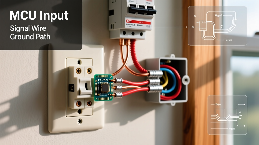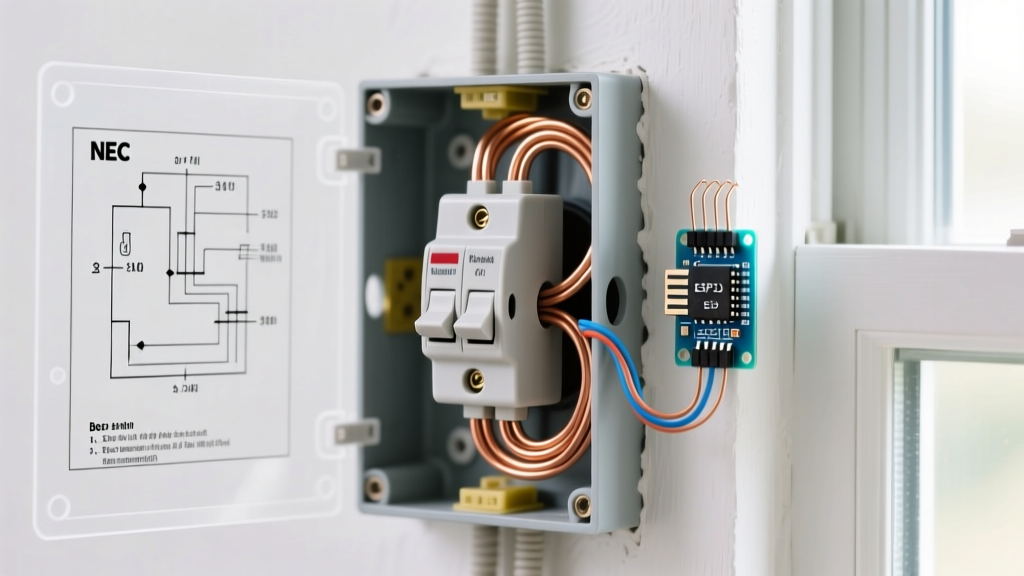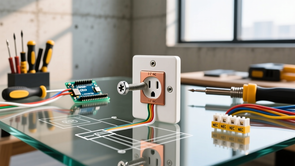

Working with 240-volt split-phase circuits requires a meticulous approach to safety and diagnostics. Unlike standard 120V household receptacles, a dryer outlet carries enough current and voltage to cause severe arc flashes, fatal shocks, or catastrophic electrical fires if mishandled. When a clothes dryer fails to operate correctly, the root cause often lies within the branch circuit wiring, the receptacle termination, or the appliance cord configuration. Relying on an accurate wiring diagram for dryer outlet setups is the only reliable way to trace voltage drops, identify miswired neutrals, and diagnose failing components.
In this comprehensive diagnostic guide, we will break down the anatomy of NEMA 10-30R and 14-30R receptacles, provide a step-by-step multimeter testing protocol, and explore the most common failure modes encountered by electricians and advanced DIYers in 2026. Whether you are dealing with a dryer that tumbles but won't heat, or a breaker that trips instantly upon startup, this troubleshooting matrix will isolate the fault.
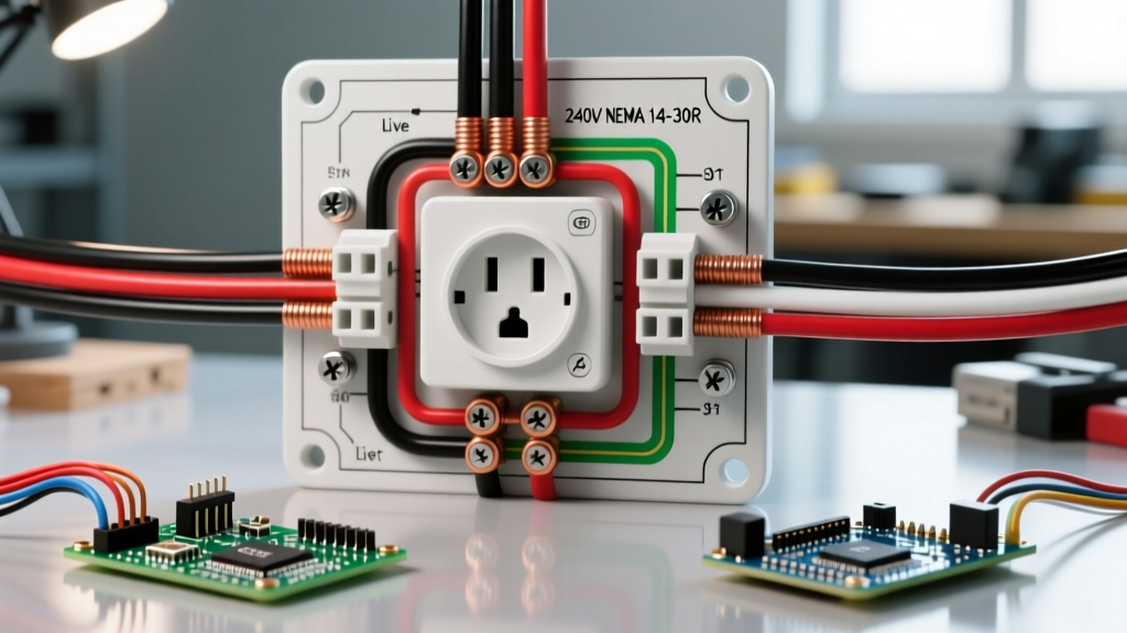
Understanding the Receptacles: NEMA 10-30R vs. NEMA 14-30R
Before pulling out a multimeter, you must identify which generation of wiring diagram for dryer outlet configurations you are dealing with. The National Electrical Code (NEC) transitioned from a 3-prong to a 4-prong standard in the 1996 code cycle, but millions of older homes still utilize the legacy 3-prong setup. Understanding the difference is critical for safe troubleshooting.
| Feature | NEMA 10-30R (Legacy 3-Prong) | NEMA 14-30R (Modern 4-Prong) |
|---|---|---|
| Hot Legs (X & Y) | Two 120V lines (240V total) | Two 120V lines (240V total) |
| Neutral (W) | Carries 120V return current AND acts as equipment ground | Dedicated current-carrying conductor for 120V loads |
| Ground (G) | None (Neutral is bonded to chassis) | Dedicated equipment grounding conductor |
| Wire Requirements | 3-wire cable (e.g., 10/3 SE or older NM) | 4-wire cable (e.g., 10/3 NM-B with bare ground) |
| NEC Status | Grandfathered for existing installations only | Required for all new construction (NEC 250.140) |
The Diagnostic Toolkit for 240V Circuits
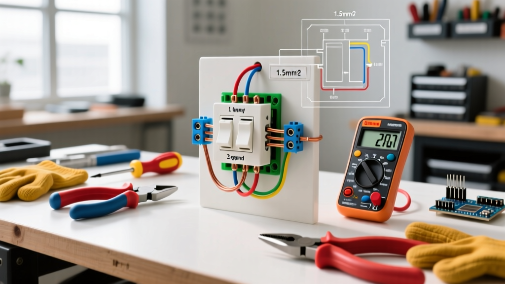
You cannot troubleshoot a 240V dryer circuit with a simple non-contact voltage tester. The thick insulation and shielding of 10 AWG cables easily block capacitive sensors, leading to false negatives. To properly execute a wiring diagram for dryer outlet diagnosis, you need professional-grade tools:
- True-RMS Digital Multimeter: A meter like the Fluke 117 or Klein Tools MM700 is essential for accurately reading split-phase voltages and detecting phantom voltages on floating neutrals.
- Insulated Screwdrivers & Nut Drivers: Rated for 1000V (e.g., Wiha or Klein Tools) to prevent accidental shorting across the bus bars if the panel cover is removed.
- Torque Screwdriver: The 2023 and 2026 NEC cycles strictly enforce torque specifications for terminations (NEC 110.14(D)). A Whia torque screwdriver set to the manufacturer's spec (usually 14-18 in-lbs for Leviton or Hubbell 30A receptacles) prevents loose connections that cause thermal melting.
- Receptacle Tester (240V specific):strong> While standard 120V testers are useless here, specialized 240V indicators can quickly verify basic hot-hot-neutral-ground orientation before bringing out the multimeter.
Troubleshooting Matrix: Symptoms and Voltage Readings
Use this matrix to correlate the physical symptoms of the dryer with the voltage readings taken at the receptacle terminals. Always test with the dryer unplugged first to verify receptacle wiring, then test under load if the circuit allows.
| Symptom | Voltage Reading (Receptacle) | Probable Cause | Diagnostic Action |
|---|---|---|---|
| Dryer is completely dead (no lights, no tumble) | 0V across L1-L2; 0V across L1-N and L2-N | Tripped breaker or severed branch circuit wire | Check breaker for mid-position trip; reset. Check panel lugs. |
| Dryer tumbles, drum light works, but NO HEAT | 120V across L1-N; 120V across L2-N; 0V across L1-L2 | One hot leg is dead (open circuit on L1 or L2) | Test breaker output. Inspect receptacle terminals for burnt/melted wire. |
| Breaker trips immediately upon plugging in dryer | N/A (Breaker won't hold) | Dead short between L1/L2 or Ground Fault | Inspect cord for crushed insulation. Verify neutral and ground are not bonded on a 4-prong cord. |
| Dryer shocks user when touching chassis | 120V measured between chassis and true ground | Missing equipment ground or reversed hot/ground | Verify continuity from receptacle ground slot to panel ground bar. |
Deep Dive: Dryer Tumbles but Won't Heat
This is the most common 240V diagnostic call. To understand why this happens, you must look at the internal wiring diagram for the dryer itself. A standard electric dryer uses 120V to power the timer, electronic control board, drum light, and the drive motor. These components are wired between one Hot leg (usually L1) and the Neutral. The heating element, however, is a massive 240V resistive load wired directly across L1 and L2.
If a homeowner reports that the dryer spins but clothes remain wet, a novice might replace the heating element or the thermal fuse. However, an expert electrician will first verify the receptacle voltage. If one of the 30-amp breaker poles has failed internally, or if one of the hot wires has backed out of the NEMA 14-30R receptacle terminal, the dryer will still receive the 120V it needs to spin the motor, but the 240V required for the heating element will be absent.
Step-by-Step Voltage Testing Protocol
- Set Multimeter: Set your True-RMS multimeter to AC Voltage (V~), ensuring the range is at least 300V.
- Test L1 to L2: Insert probes into the two slanted hot slots of the NEMA 14-30R. You should read between 235V and 245V. If you read 0V or 120V, you have a dropped leg.
- Test L1 to Neutral: Insert one probe into the first hot slot and the other into the L-shaped neutral slot. Reading must be ~120V.
- Test L2 to Neutral: Insert one probe into the second hot slot and the other into the neutral slot. Reading must be ~120V.
- Test Neutral to Ground: Measure between the Neutral (W) and Ground (G) slots. This should read 0V to 2V. A reading of 120V here indicates a severe miswiring condition where a hot leg is tied to neutral or ground.
The 3-Prong to 4-Prong Conversion Trap
According to the National Fire Protection Association (NFPA), the NEC strictly prohibits using the neutral conductor as an equipment ground for new installations. However, when homeowners move from an older apartment with a NEMA 10-30R to a new build with a NEMA 14-30R, they must change the dryer's power cord. This is where a lethal mistake frequently occurs.
CRITICAL SAFETY WARNING: When installing a 4-prong cord on a dryer originally shipped with a 3-prong cord, you MUST remove the internal bonding strap or bonding wire that connects the neutral terminal to the dryer's metal chassis. Failing to remove this strap creates a parallel neutral path, energizing the chassis and violating NEC Article 250.142.
If the bonding strap is left in place on a 4-prong setup, any imbalance in the 120V loads (like the timer or motor) will cause current to flow on the bare ground wire. Worse, if the dedicated neutral wire in the wall ever becomes disconnected, the dryer's metal chassis will become energized with 120V, waiting for a user to touch it and complete the circuit to the floor. Always consult the manufacturer's specific wiring diagram located on the back of the dryer's access panel to verify the bonding strap has been severed or removed.
Receptacle Replacement and Termination Specs
If your voltage testing reveals that the receptacle itself is the point of failure—often evidenced by melted plastic, a burnt smell, or loose blade tension—it must be replaced. For 30-amp dryer circuits, you must use a heavy-duty, industrial-grade receptacle. Avoid the cheapest builder-grade options found in big-box stores; instead, opt for commercial-grade models like the Leviton 278-S00 or the Hubbell HBL2620, which feature robust brass contacts and high-temperature thermoplastic housings.
When terminating 10 AWG copper wire to the new NEMA 14-30R:
- Strip Length: Strip exactly 5/8 inch of insulation. Do not nick the copper conductor, which creates a weak point that will snap under thermal expansion cycles.
- Wire Orientation: Ensure the bare ground wire is routed to the green grounding screw, the white neutral to the silver/white terminal, and the two black/red hots to the brass terminals. The hot legs are interchangeable on a 240V circuit; there is no 'polarity' between L1 and L2.
- Torque Verification: As highlighted by the Electrical Safety Foundation International (ESFI), loose connections are a leading cause of residential electrical fires. Use a calibrated torque screwdriver to tighten the terminal screws to the exact value printed on the receptacle's specification sheet (typically 14 to 18 inch-pounds). Hand-tightening is no longer acceptable under modern electrical inspection standards.
Final Diagnostic Considerations
Troubleshooting a 240V dryer circuit requires a systematic elimination of variables. By cross-referencing the physical symptoms with the exact voltage readings dictated by the wiring diagram for dryer outlet configurations, you can confidently isolate whether the fault lies in the breaker panel, the branch circuit wiring, the receptacle termination, or the appliance cord. Always prioritize personal protective equipment (PPE), verify your multimeter on a known live source before and after testing, and never bypass safety grounding mechanisms to force an older appliance to work on a modern circuit.