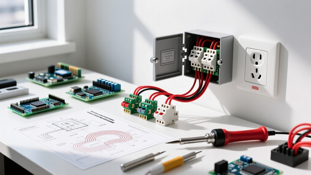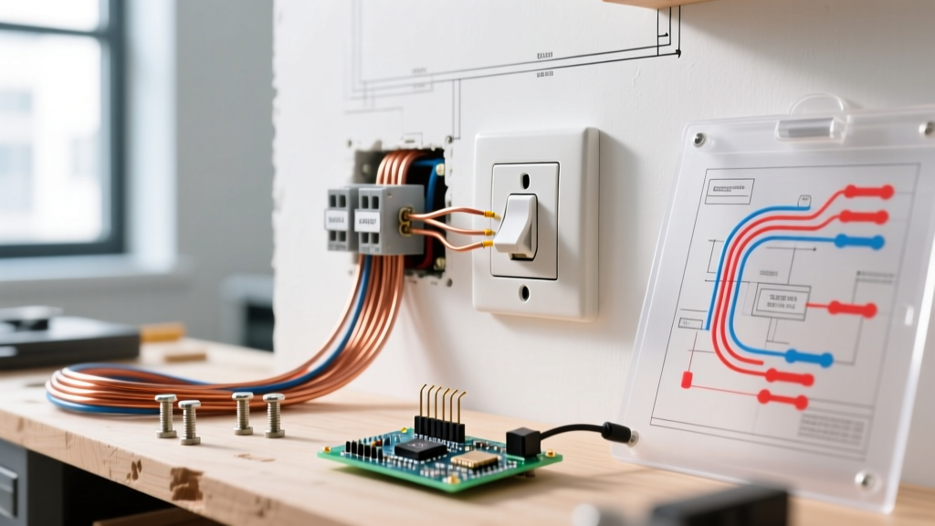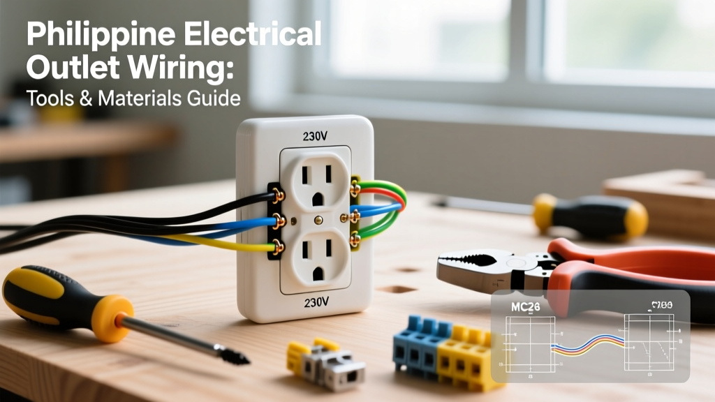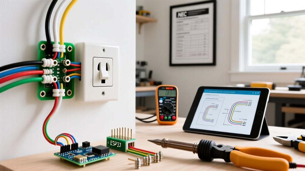

The Complete Guide to Adding an Electrical Outlet on Wall Drywall
Adding a new electrical outlet on wall surfaces is one of the most practical DIY electrical upgrades you can undertake. Whether you are eliminating an extension cord hazard behind a wall-mounted TV, adding power to a new home office desk, or upgrading a kitchen backsplash, retrofitting a receptacle requires precision, an understanding of circuit load limits, and strict adherence to modern safety codes. In 2026, with the widespread adoption of the 2023 National Electrical Code (NEC) across most US jurisdictions, the requirements for Arc-Fault Circuit Interrupter (AFCI) and Ground-Fault Circuit Interrupter (GFCI) protection have expanded, making it critical to understand exactly what type of device you are installing and where.
This step-by-step installation guide focuses on the most common residential scenario: tapping into an existing circuit to install a new 15-amp or 20-amp duplex receptacle using an "old work" (retrofit) electrical box. We will cover box fill calculations, precise wire stripping measurements, and the mechanical differences between side-wiring and back-wiring to ensure a connection that will not fail under thermal expansion.
2026 NEC Compliance & Safety Prerequisites
Before cutting into your drywall, you must verify that the circuit you are tapping into can handle the additional load and meets current code requirements. According to the National Fire Protection Association (NFPA), general lighting and receptacle circuits are calculated at 180 volt-amperes per outlet. A standard 15-amp breaker should ideally serve no more than 8 to 10 receptacles to prevent nuisance tripping, though the NEC does not specify a hard limit for residential dwelling units.
Critical Code Update: As of 2026, NEC Article 210.12 requires AFCI protection for almost all 120-volt, single-phase, 15- and 20-amp branch circuits supplying outlets in living rooms, bedrooms, kitchens, and hallways. If your existing panel does not have an AFCI breaker for the circuit you are extending, you must install an AFCI/GFCI dual-function breaker or use an OBC (Outlet Branch Circuit) AFCI receptacle at the first point of entry in the daisy chain.
Required Tools and Materials Matrix
Using the correct materials prevents overheating and mechanical failure. Below is a curated list of professional-grade components and their estimated 2026 retail costs.
| Category | Specific Product / Model | Purpose & Specifications | Est. Cost |
|---|---|---|---|
| Retrofit Box | Carlon B114R-UPC | 1-Gang, 14 cu. in. PVC Old Work Box. Meets NEC 314.16 box fill requirements for up to four 12 AWG cables. | $1.25 |
| Receptacle | Leviton T5250 (15A) or T5262 (20A) | Tamper-Resistant (TR) Duplex. Features screw-clamp back-wiring for superior terminal grip. | $1.85 |
| Cable | Southwire 14/2 or 12/2 NM-B | Non-metallic sheathed cable with bare copper ground. Match gauge to breaker size (14 AWG for 15A, 12 AWG for 20A). | $0.65/ft |
| Voltage Tester | Milwaukee 48-22-8426 | Dual-range non-contact voltage detector with LED flashlight and audible alarm. | $24.00 |
| Wire Strippers | Klein Tools 11055 | Precision shears with specific gauge holes to prevent nicking the copper conductor. | $28.00 |
Step 1: Circuit Mapping and Power Verification
The U.S. Consumer Product Safety Commission (CPSC) reports that electrical receptacles are involved in thousands of home fires annually, often due to DIYers working on live circuits or misidentifying shared neutrals. Never assume a wall is dead just because the light switch is off.
- Identify the Source: Locate an existing outlet on the wall where you want to add power. Plug in a lamp or radio to confirm it works, then go to your main service panel and turn off the corresponding breaker.
- Verify Zero Energy: Insert your Milwaukee non-contact voltage tester into both the top and bottom slots of the hot side (the shorter slot) of the existing outlet. The tool must remain completely silent and unlit.
- Test the Tester: Always verify your tester is functioning by testing it on a known live circuit (like a different room) before and after checking the target outlet.
Step 2: Stud Location and Drywall Cutout
When adding an electrical outlet on wall drywall, you must avoid drilling into structural studs, plumbing, or existing wiring.
- Scan for Obstructions: Use a magnetic or density-based stud finder (e.g., Franklin Sensors 710) to locate the edges of the wall studs. You want to place your new box in the center of a stud bay (typically 14.5 inches of clear space between 16-inch on-center studs).
- Trace the Box: Hold the Carlon B114R-UPC old work box against the drywall, ensuring it is perfectly level. Trace the outside perimeter with a pencil. Do not trace the flange; trace only the main body of the box.
- Cut the Opening: Using a drywall keyhole saw (Klein Tools 56207), pierce the drywall inside the traced line and carefully cut along the perimeter. Score the drywall paper on the backside to ensure a clean snap if using a utility knife.
Step 3: Fishing the NM-B Cable
Routing the cable from the source outlet to the new cutout requires patience to avoid damaging the wire insulation inside the wall cavity.
- Prepare the Source Box: Remove the existing receptacle from the source box. Identify a knockout that leads toward the new outlet location. If the box is full, you may need to replace it with a deeper 2-gang or 4-inch square box to meet NEC box fill calculations.
- Use Fiberglass Fish Tapes: Avoid steel fish tapes near live panels or existing wiring, as they can conduct electricity if they nick a live wire. Use a non-conductive fiberglass fish tape (Klein 56332).
- Feed and Retrieve: Push the fish tape through the knockout from the source box up into the wall cavity. From your new drywall cutout, insert a bent piece of stiff wire (a "hook") to catch the fish tape. Pull the tape out of the new hole, attach your NM-B cable, and pull it back to the source box.
- Leave Slack: Ensure you have at least 8 inches of cable protruding from both the source and the new cutout, as required by NEC 300.14.
Step 4: Mounting the Old Work Box
- Prep the Cable: Use your utility knife to slit the outer PVC jacket of the NM-B cable. Strip back the jacket so that exactly 1/4 inch of the sheathing enters the inside of the electrical box. The paper separator should be torn off.
- Thread the Box: Feed the stripped cable through the integrated cable clamp on the back of the Carlon B114R-UPC box.
- Secure to Drywall: Push the box into the drywall cutout. Tighten the two mounting screws on the face of the box. As you tighten, the internal PVC "wing" clamps will rotate and pull tight against the back of the drywall. Stop tightening the moment the box is flush and secure; over-tightening will crack the drywall or strip the PVC threads.
Step 5: Precision Wiring (Side-Wire vs. Back-Wire)
This is where most DIY failures occur. The Electrical Safety Foundation International (ESFI) emphasizes that poor terminal connections cause high-resistance faults, leading to arcing and fires. You must choose the correct termination method.
The Danger of Push-In Back-Stabbing
Cheap contractor-grade receptacles feature "push-in" holes on the back. These rely on a small brass spring clip to grip the wire. They are only rated for 14 AWG solid copper, and over time, thermal expansion and contraction can loosen the grip, causing arcing. Never use push-in back-stabs.
The Professional Standard: Screw-Clamp Back-Wiring
Premium devices like the Leviton T5250 feature a pressure plate back-wiring system. When you insert the stripped wire into the back hole and tighten the side screw, a heavy-duty brass plate clamps down on the wire. This provides the speed of back-wiring with the mechanical security of a side-wire loop.
- Strip to Exact Length: Use the built-in gauge on the back of the Leviton receptacle. For 14 or 12 AWG wire, this is typically 3/4 inch of bare copper. If you strip too much, you will have exposed copper outside the terminal (a shock hazard). If you strip too little, the insulation will be trapped under the clamp (an open-circuit hazard).
- Connect Ground: Loop the bare copper ground wire clockwise around the green ground screw. Tighten firmly.
- Connect Neutral (White): Insert the white wire into the back-wire hole aligned with the silver terminal screws. Tighten the screw until the pressure plate secures the wire.
- Connect Hot (Black): Insert the black wire into the back-wire hole aligned with the brass terminal screws. Tighten securely.
Step 6: Device Mounting and Final Testing
- Fold the Wires: Gently fold the wires into the back of the box in a "Z" or accordion pattern. Do not just shove them in, as this can pinch the ground wire against the hot terminal.
- Mount the Receptacle: Secure the Leviton receptacle to the box using the provided 6-32 machine screws. Ensure the strap sits flush against the drywall. If the box is slightly recessed, use nylon outlet shims (Catas 1850) behind the mounting ears to prevent the faceplate from cracking when tightened.
- Install Faceplate and Restore Power: Attach a standard nylon or polycarbonate faceplate. Turn the breaker back on at the panel.
- Verify Wiring: Plug in a Klein Tools RT250 GFCI receptacle tester. You should see two yellow lights indicating "Correct" wiring. Press the black GFCI test button on the tester to ensure the upstream breaker trips (if AFCI/GFCI protected) or the device trips (if it is a GFCI receptacle).
Troubleshooting Common Installation Failure Modes
If your receptacle tester shows an error, consult this matrix before calling an electrician.
| Tester Reading | Probable Cause | Corrective Action |
|---|---|---|
| Open Ground | Bare copper wire not making contact with the green screw, or ground wire severed inside the wall cavity during fishing. | Remove device, check ground loop tension. If wire is damaged, pull new cable. |
| Open Neutral | White wire insulation was stripped too short, causing the pressure plate to clamp on the PVC jacket instead of the copper. | Turn off power, remove neutral, re-strip to exactly 3/4 inch, and re-terminate. |
| Hot/Neutral Reversed | Black wire connected to silver terminal, white wire connected to brass terminal. | Swap the wires. This is a severe shock hazard as the appliance switch will only break the neutral, leaving the device internally energized. |
| Breaker Trips Instantly | Hot and ground wires are touching inside the box, or a staple pierced the NM-B jacket inside the wall. | Inspect box for pinched wires. If wires are fine, the damage is inside the wall and the cable must be replaced. |
Final Safety Reminder
Adding an electrical outlet on wall drywall is a highly rewarding project that increases your home's functionality and safety. However, electricity is unforgiving. If your home features aluminum wiring (common in homes built between 1965 and 1973), you must use CO/ALR rated devices and apply antioxidant paste, or hire a licensed professional to perform pigtailing. Always pull a local permit for electrical modifications; it ensures your work is inspected and protects your homeowner's insurance coverage in the event of an electrical fire.