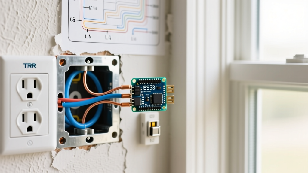

Mastering the Fundamentals: How to Install an Electrical Outlet
Knowing how to install an electrical outlet is a foundational skill for any DIY enthusiast or apprentice electrician. While swapping a broken receptacle seems straightforward, improper wiring remains a leading cause of residential electrical fires. According to the U.S. Consumer Product Safety Commission (CPSC), electrical receptacles are involved in thousands of fires annually, often due to loose connections, reversed polarity, or overloaded circuits.
This wiring diagram reference goes beyond basic tutorials. We will break down the exact terminal anatomy, torque specifications, and National Electrical Code (NEC) requirements for standard 15-amp and 20-amp duplex receptacles, as well as GFCI configurations. Whether you are wiring an end-of-run outlet or daisy-chaining a middle-of-run circuit, this guide provides the technical depth required for a safe, code-compliant installation.
⚠️ CRITICAL SAFETY WARNING: Always turn off the power at the main circuit breaker panel before beginning any electrical work. Verify the circuit is dead using a non-contact voltage tester (NCVT) and a multimeter. Never rely solely on a wall switch to isolate power.Essential Tools and Material Specifications
Professional results require professional-grade tools. Avoid cheap, uncalibrated wire strippers that can nick the copper conductor, creating a weak point that will eventually overheat.
- Wire Strippers: Klein Tools 11055 (for 10-20 AWG solid and stranded wire).
- Voltage Tester: Ideal SureTrace or Fluke 1AC-II non-contact voltage tester.
- Torque Screwdriver: CDI 401SM or Klein Tools 32500. NEC 110.14(D) mandates that connections be torqued to the manufacturer's specifications.
- Wire Connectors: Ideal Twister 341 (purple) for pigtailing up to three #12 AWG wires.
- Receptacle: Specification-grade duplex receptacle (e.g., Leviton 5262-W or Pass & Seymour 5262-X). Avoid "builder-grade" or "residential-grade" receptacles, as their internal contact springs degrade faster under heavy loads.
Decoding the Duplex Receptacle Terminal Layout
Before wiring, you must understand the physical layout of a standard NEMA 5-15R or 5-20R duplex receptacle. The device features three distinct terminal sections:
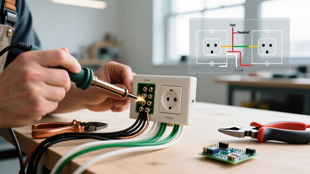
- Brass Screws (Hot/Line): Connect the black (or red) ungrounded conductor here. These screws are connected to the shorter slot on the face of the receptacle.
- Silver Screws (Neutral): Connect the white grounded conductor here. These correspond to the longer vertical slot.
- Green Screw (Ground): Connect the bare copper or green insulated equipment grounding conductor (EGC) here. This corresponds to the U-shaped pin.
Pro-Tip: Notice the small metal "fin" connecting the two brass screws and the two silver screws. If you are installing a split-receptacle (where the top and bottom outlets are on different breakers, common in older kitchens), you must snap off the brass fin using needle-nose pliers. For standard wiring, leave both fins intact.
Wiring Diagram 1: End-of-Run Standard Outlet
An "end-of-run" outlet is the last receptacle on a circuit branch. Only one set of cables (one hot, one neutral, one ground) enters the electrical box.
Step-by-Step Execution
- Strip the Wires: Use the gauge-specific hole on your wire strippers to remove exactly 3/4 inch of insulation from the black and white wires. Stripping too little leaves exposed insulation under the screw head; stripping too much leaves bare, live copper exposed outside the terminal.
- Form the J-Hook: Bend the stripped ends into a clockwise "J-hook" using the looping hole on your wire strippers.
- Connect Ground: Loop the bare copper wire clockwise around the green ground screw. Tighten to 14 in-lbs.
- Connect Neutral: Loop the white wire clockwise around one of the silver screws. The clockwise direction ensures that tightening the screw pulls the loop tighter, rather than pushing it out.
- Connect Hot: Loop the black wire clockwise around one of the brass screws.
- Torque and Verify: Use your torque screwdriver set to the manufacturer's spec (typically 14 in-lbs for 12 and 14 AWG wire on spec-grade receptacles) to secure all terminals.
Wiring Diagram 2: Middle-of-Run with Pigtailing
A "middle-of-run" outlet sits between the breaker panel and other downstream outlets. You will have two cables entering the box: one bringing power in, and one carrying power out. While you can connect both hot wires to the brass screws and both neutrals to the silver screws, this "daisy-chaining" method is strongly discouraged for the neutral wire.
NEC Insight: Relying on the receptacle's internal metal strap to carry the neutral current to downstream devices violates the spirit of NEC 300.13(B). If the receptacle fails or is removed for painting, the downstream neutral is severed, which can cause severe overvoltage conditions on multi-wire branch circuits (MWBCs).
The Pigtailing Method (Best Practice)
Pigtailing involves joining the incoming and outgoing wires together with a short piece of scrap wire (the "pigtail"), which then connects to the receptacle.
- Step 1: Cut two 6-inch pigtails (one black, one white) using the same gauge wire as the circuit (12 AWG for 20A, 14 AWG for 15A).
- Step 2: Strip 3/4 inch of insulation from both ends of the pigtails.
- Step 3: Group the incoming black wire, outgoing black wire, and the black pigtail together. Twist them tightly with linemans pliers and secure with an Ideal Twister 341 wire nut.
- Step 4: Repeat for the white neutral wires.
- Step 5: Connect the bare ground wires together with a green grounding wire nut, leaving a pigtail for the receptacle's green screw. Alternatively, use a crimp-on ground sleeve if local codes permit.
- Step 6: Connect the single black pigtail to the brass screw and the single white pigtail to the silver screw.
Wiring Diagram 3: GFCI Receptacle Line and Load
Ground Fault Circuit Interrupter (GFCI) receptacles are mandated by the National Fire Protection Association (NFPA) in areas where water and electricity may intersect, including kitchens, bathrooms, garages, and outdoor patios. GFCIs monitor the current balance between the hot and neutral wires, tripping in milliseconds if a leakage of 4 to 6 milliamps is detected.
Understanding LINE vs. LOAD Terminals
Unlike standard receptacles, GFCIs have two distinct sets of terminals marked on the back of the device:
- LINE Terminals: These connect to the incoming power source from the breaker panel. If you only have one cable entering the box, it always connects to the LINE.
- LOAD Terminals: These connect to the outgoing cable that feeds downstream standard receptacles. Wiring downstream outlets to the LOAD terminals extends GFCI protection to those outlets as well.
NEC Code Matrix: Wire Gauge, Breaker, and Torque
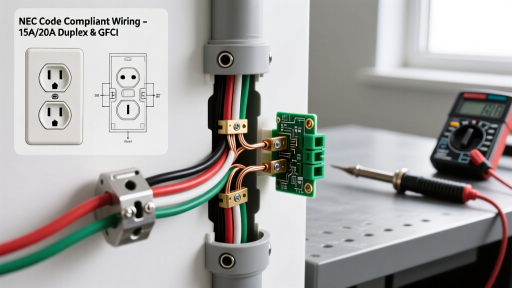
Adhering to the correct wire gauge and breaker pairing is non-negotiable for fire prevention. Furthermore, as of recent NEC cycles, torque verification is strictly enforced by inspectors. Reference the matrix below for standard residential branch circuits:
| Circuit Rating | Minimum Wire Gauge (Copper) | Max Breaker Size | Receptacle Rating | Terminal Torque Spec |
|---|---|---|---|---|
| 15 Amp | 14 AWG | 15 Amp | 15 Amp (NEMA 5-15R) | 14 in-lbs (1.6 N-m) |
| 20 Amp | 12 AWG | 20 Amp | 15A or 20A (NEMA 5-20R) | 14 in-lbs (1.6 N-m) |
| 30 Amp | 10 AWG | 30 Amp | N/A (No standard 15/20A receptacles allowed) | 35 in-lbs (4.0 N-m) |
Note: A 20-amp circuit is legally permitted to have 15-amp receptacles installed on it, provided there is more than one receptacle on the circuit (NEC 210.21(B)(3)). However, if it is a single-receptacle circuit, the receptacle must be rated for 20 amps.
Box Fill Calculations: Avoiding Overcrowding
When installing an electrical outlet, you must ensure the electrical box has adequate volume. Overcrowded boxes cause wires to pinch, damaging insulation and creating short-circuit hazards. According to NEC 314.16, you must calculate the "box fill" based on the largest wire in the box.
- 14 AWG Wire: Requires 2.0 cubic inches per conductor.
- 12 AWG Wire: Requires 2.25 cubic inches per conductor.
- 10 AWG Wire: Requires 2.5 cubic inches per conductor.
How to count: Each hot and neutral wire counts as one allowance. All equipment grounding wires combined count as one allowance. The receptacle device itself counts as two allowances. All internal clamps count as one allowance. Multiply the total allowances by the cubic inch value of the largest wire to find the minimum required box volume. A standard "single gang" deep plastic box typically offers 22.5 cubic inches, which is usually sufficient for a standard middle-of-run 12 AWG wiring scenario.
Common Failure Modes and Troubleshooting
Even with correct diagrams, physical installation errors can cause immediate or delayed failures. Consult this troubleshooting guide if your outlet fails testing:
1. Reversed Polarity
Symptom: A plug-in circuit tester shows the "Hot/Neutral Reverse" light pattern.
Cause: The black wire was connected to the silver screw, and the white wire to the brass screw.
Fix: Turn off the breaker, swap the wires to their correct terminal colors. This is a severe shock hazard, as the appliance's internal switch will only disconnect the neutral, leaving the device energized even when "off."
2. Open Ground
Symptom: Tester indicates no ground connection.
Cause: The bare copper wire was not securely fastened to the green screw, or the grounding path back to the panel is broken.
Fix: Verify the ground wire is tightly torqued to the receptacle. If wiring in an older home with no ground wire present in the box, NEC 406.4(D) allows you to install a GFCI receptacle and label it "No Equipment Ground," but you cannot manufacture a fake ground by bootlegging it to the neutral wire.
3. Arcing and Melted Terminals
Symptom: Discoloration, melting plastic smell, or intermittent power.
Cause: "Back-stabbing" or using the push-in quick-wire connectors on the back of builder-grade receptacles. These spring-loaded connections lose tension over time, increasing resistance and generating immense heat.
Fix: Never use push-in terminals. Always use the side-screw terminals or the "back-wire" clamping plates found on specification-grade receptacles, torqued to the exact manufacturer specification. For further reading on workplace and residential electrical safety standards, refer to the Occupational Safety and Health Administration (OSHA) electrical guidelines.
Final Testing and Commissioning
Once the receptacle is secured to the box and the faceplate is installed, restore power at the breaker. Use a high-quality plug-in tester (such as the Gardner Bender GFI-3501) to verify correct wiring. Press the "Test" button on the tester to ensure the breaker or GFCI trips appropriately. Finally, use a multimeter to verify the voltage reads between 118V and 122V across the hot and neutral slots. Proper installation isn't just about making the outlet work; it's about ensuring it operates safely for decades under varying load conditions.