
The Inspector’s Lens: Why Outlet Box Installations Fail
When learning how to install electrical outlet box assemblies correctly, most DIYers and junior apprentices focus solely on the wiring. However, from an electrical inspector's perspective, the physical box installation is where the majority of National Electrical Code (NEC) violations occur. A poorly mounted or undersized box creates heat buildup, device strain, and severe fire hazards. This guide approaches the installation process through the rigorous lens of a municipal electrical inspection, ensuring your rough-in and final trim-out pass on the first visit.
Phase 1: Rough-In Box Selection and Placement
The inspection begins before a single wire is stripped. Selecting the correct enclosure for the environment and application is critical. For standard interior drywall applications, the Carlon B618R (an 18 cubic inch non-metallic new-work box, typically ~$1.40) is the industry standard. For retrofit or old-work scenarios, the Raco 175 (a 4x1.5-inch metallic old-work box, ~$3.20) provides the necessary structural rigidity via integrated mounting wings.
Knockout Management and Sealing
Inspectors strictly enforce NEC 314.12 and 110.12 regarding unused openings. If you punch out a knockout to feed a cable and later reroute it, that open hole must be sealed with a listed knockout seal (e.g., Gardner Bender GK-5). Leaving a 1/2-inch or 3/4-inch knockout open exposes the interior of the wall cavity to dust, debris, and potential fire draft paths, resulting in an automatic fail.
Phase 2: Box Fill Calculations (NEC Article 314.16)
Overcrowding a box is a thermal hazard. Wires generate heat under load; if the box volume is insufficient, that heat cannot dissipate, degrading insulation over time. Inspectors calculate box fill based on the largest conductor entering the box.
| Conductor Size (AWG) | Volume Allowance per Wire | Typical Application |
|---|---|---|
| 14 AWG | 2.0 cu. in. | 15A Lighting & Receptacle Circuits |
| 12 AWG | 2.25 cu. in. | 20A Kitchen, Bath, & Garage Circuits |
| 10 AWG | 2.5 cu. in. | 30A Dryer or Water Heater (Rare in standard outlet boxes) |
Real-World Calculation Example
Imagine installing a standard 15A duplex receptacle on a 12 AWG circuit (passing power to the next outlet). You have two 12 AWG cables entering the box (4 current-carrying wires total), plus two equipment grounding wires, one internal cable clamp, and the receptacle device itself.
- Current-carrying wires: 4 wires × 2.25 cu. in. = 9.0 cu. in.
- Grounding wires: 1 allowance (all grounds count as one) × 2.25 = 2.25 cu. in.
- Internal clamps: 1 allowance × 2.25 = 2.25 cu. in.
- Device (receptacle): 2 allowances × 2.25 = 4.5 cu. in.
- Total Required Volume: 18.0 cubic inches.
In this scenario, a standard 18 cu. in. box is exactly at the legal limit. If you add a pigtail or a smart switch with a bulky module, you will violate NEC 314.16 and fail inspection. Always upsize to a 22 cu. in. deep box (like the Carlon B625R) when dealing with 12 AWG feed-throughs.
Phase 3: Mounting Tolerances and Flush Requirements
How you secure the box to the framing dictates the final aesthetic and safety of the installation. NEC 314.20 dictates the strict tolerances for flush mounting.
Inspector's Note: 'In non-combustible surfaces like concrete, tile, or plaster, the box can be set back no more than 1/4 inch (6 mm). In combustible surfaces like wood or drywall, the box must be flush or project outward. A recessed box in drywall creates a gap where heat and arcing can ignite the paper facing.'
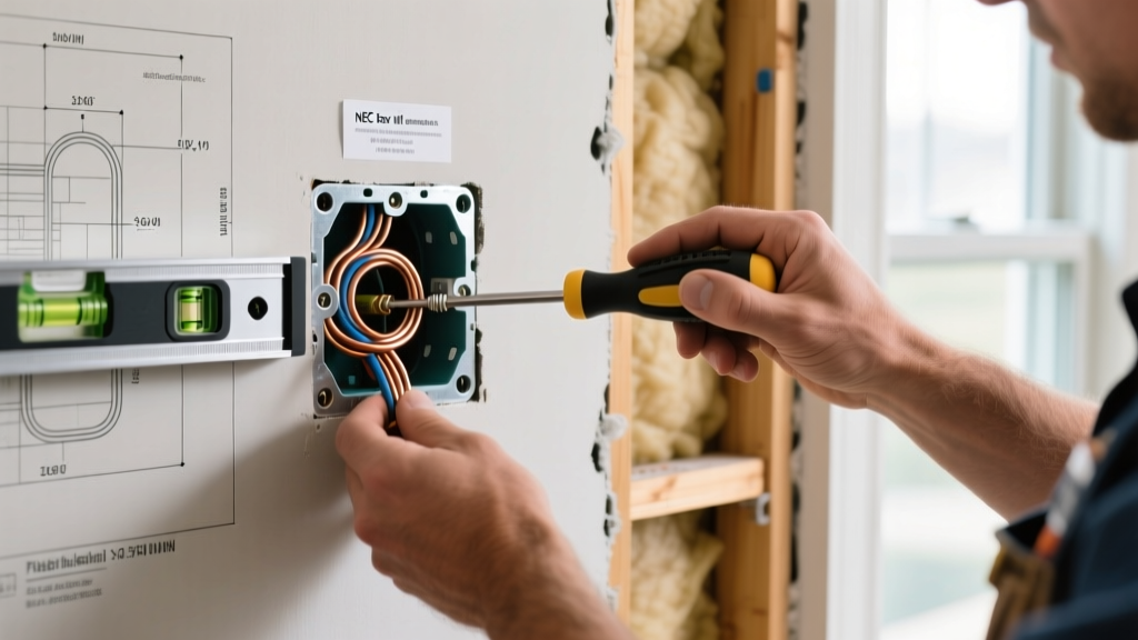
When learning how to install electrical outlet box units in existing drywall, use a RotoZip with a drywall bit to cut the opening. Ensure the old-work box's flip wings or madison clips are fully engaged against the back of the drywall. Torque the mounting screws to exactly 10-15 inch-pounds; over-tightening will warp the drywall or strip the plastic ears on non-metallic boxes.
Phase 4: Final Inspection and Device Testing
Once the drywall is finished and the device is wired, the final inspection requires specific testing protocols to verify the integrity of the box and connection.
- Visual Yoke Alignment: Verify the receptacle yoke sits perfectly flush against the box mounting ears. Use box extender rings (e.g., Caddy BR1) if the gap exceeds 1/8 inch.
- Ground Path Continuity: For metallic boxes (like the Raco 175), test the continuity between the receptacle's green grounding screw and the bare copper ground wire using a multimeter. Resistance must read near 0.0 ohms.
- Polarity and GFCI Verification: Insert a Klein Tools RT250 GFCI Receptacle Tester. The RT250 doesn't just check standard wiring; it actively trips the GFCI circuit to verify the mechanical function of the test button without relying on the internal electronics of the receptacle.
- Torque Verification: Inspectors increasingly require torqued terminal screws. Use a Wiha 60601 VDE Torque Screwdriver set to the manufacturer's specification (usually 14-16 inch-pounds for standard 15A/20A receptacles) to ensure wires will not loosen due to thermal expansion cycles.
Common Failure Modes and Edge Cases
Even experienced electricians trip on specific edge cases during municipal inspections. Review the National Electrical Code (NEC) guidelines regularly, as local amendments frequently update enforcement priorities.
1. The 'Plaster Ear' Violation
Leaving the break-away plaster ears intact on a receptacle when mounting to a standard single-gang box prevents the device yoke from seating flush against the box metal or plastic. This causes the device to rock when plugs are inserted, eventually loosening the terminal connections. Always snap them off unless you are using a specific mud ring that requires them.
2. Grounding Metallic Boxes Without a Pigtail
If you are using a metallic box and a metallic faceplate, the receptacle's grounding screw might make contact with the box, but inspectors require a dedicated grounding pigtail from the wire nut splice to the metallic box's 10-32 ground screw. Relying solely on the device yoke for box grounding is a violation of OSHA electrical safety standards and NEC 250.148.
3. Fire-Rated Wall Penetrations
When installing an outlet box in a fire-rated assembly (like a garage-to-house separation wall), the box must be listed for fire resistance. Furthermore, if boxes are installed on opposite sides of a fire wall, they must be separated by a minimum horizontal distance of 24 inches to maintain the wall's fire-resistance rating, unless protected by a listed intumescent fire putty pad (such as 3M Fire Barrier Putty).
Frequently Asked Questions (FAQ)
Can I use a metallic box with non-metallic (NM-B) Romex cable?
Yes. However, you must use listed non-metallic cable connectors (like the Arlington NM711) to secure the Romex to the metallic box knockout. Pushing the bare cable through the knockout without a connector will slice the insulation on the sharp metal edge, causing a ground fault or short circuit that will fail final testing.
What happens if my drywall hole is cut too large for the old-work box?
If the gap around the box exceeds the yoke's coverage, you must patch the drywall or use an oversized faceplate (often called a 'goof plate'). Inspectors will fail an installation if the combustible drywall paper is exposed inside the gap around a metallic box, as arcing could ignite the paper facing.
Summary Checklist for Passing Inspection
- Box volume mathematically verified against NEC 314.16.
- All unused knockouts sealed with listed fittings.
- Box mounted flush (combustible) or max 1/4-inch recessed (non-combustible).
- Metallic boxes independently grounded via 10-32 green screw.
- Terminal screws torqued to manufacturer specifications.
- Device tested with a solenoid-based or advanced GFCI tester.
Mastering how to install electrical outlet box hardware is about more than just making the power turn on. By adopting the meticulous testing and inspection frameworks outlined by organizations like the International Association of Electrical Inspectors (IAEI), you ensure your installation is safe, code-compliant, and built to last decades without thermal degradation.