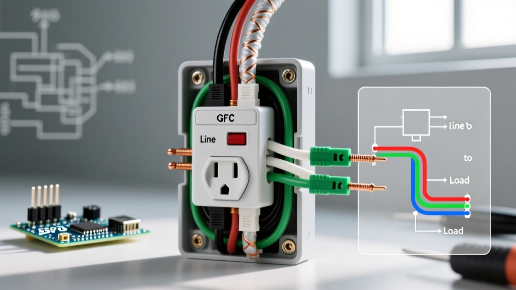

Understanding the Core Wiring Diagram for GFCI Receptacle Installations
Installing a Ground Fault Circuit Interrupter (GFCI) is one of the most critical safety upgrades you can perform in a residential or commercial electrical system. According to the National Electrical Code (NEC), GFCI protection is now mandated in virtually all damp, wet, and outdoor locations, including kitchens, bathrooms, garages, and crawl spaces. However, the physical installation is only half the battle; understanding the correct wiring diagram for GFCI receptacle configurations is what ensures the device actually protects the circuit and prevents nuisance tripping.
Unlike standard duplex receptacles that simply pass current through, a GFCI monitors the current differential between the hot and neutral conductors. If an imbalance as small as 4 to 6 milliamps is detected—indicating current is leaking to ground, potentially through a human body—the internal solenoid trips the circuit in under 25 milliseconds. This guide breaks down the exact wiring schematics, terminal identifications, and edge cases you need to know for a flawless 2026 installation.
The Golden Rule: Line vs. Load Terminals
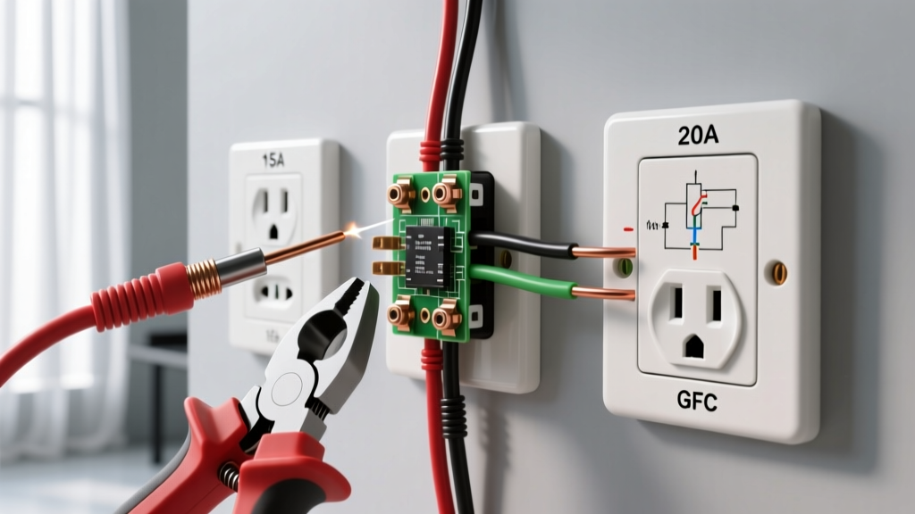
The most common point of failure in GFCI installations is confusing the LINE and LOAD terminals. Every standard 15A and 20A GFCI receptacle features two distinct sets of screw terminals, usually separated by a yellow or red warning tape on new devices.
CRITICAL SAFETY RULE: The LINE terminals receive power from the breaker panel. The LOAD terminals send protected power downstream to other standard receptacles. Reversing these will result in a receptacle that has power but offers ZERO ground-fault protection, while simultaneously failing the built-in self-test.
Identifying Your Wires Before Connection
- Hot (Line): Typically black or red. Connects to the brass LINE screw.
- Neutral (Line): Typically white. Connects to the silver LINE screw.
- Ground: Bare copper or green. Connects to the green grounding screw at the bottom of the yoke.
- Downstream Hot (Load): Connects to the brass LOAD screw (only if protecting downstream devices).
- Downstream Neutral (Load): Connects to the silver LOAD screw.
Scenario A: Single-Location Protection (Line Only)
Use this wiring diagram when the GFCI is at the end of a circuit run, or when you only need to protect the specific outlet without extending protection to downstream devices. This is common in older homes where bathroom circuits are not daisy-chained.
- Verify Power is Off: Use a non-contact voltage tester and a multimeter to confirm 0V at the box.
- Strip the Wires: Use a wire stripper to remove exactly 3/4 inch of insulation from the black, white, and ground wires. Do not nick the copper conductor.
- Connect the Ground: Loop the bare copper wire clockwise around the green grounding screw. Tighten to 14 in-lbs.
- Connect the Line Hot: Attach the black wire to the brass screw marked 'LINE'.
- Connect the Line Neutral: Attach the white wire to the silver screw marked 'LINE'.
- Cap the Load Terminals: Leave the LOAD terminals empty. Wrap the device in electrical tape to cover the exposed terminal screws before pushing it into the box.
Scenario B: Multi-Location Downstream Protection (Line and Load)
If your wiring diagram requires the GFCI to protect standard duplex receptacles further down the circuit (e.g., a kitchen countertop run), you must utilize the LOAD terminals. This feed-through method saves money and panel space, as one $22 GFCI can protect three or four standard $3 receptacles.
- Identify the incoming power cables (LINE) and the outgoing cables heading to the next outlet (LOAD) using a voltage tester before disconnecting the old wiring.
- Connect the incoming black and white wires to the brass and silver LINE screws, respectively.
- Connect the outgoing black and white wires to the brass and silver LOAD screws.
- Pro-Tip: Never pigtail the LOAD neutral. The GFCI's internal sensing coil requires the downstream neutral to pass directly through the LOAD terminal to accurately monitor the returning current.
2026 GFCI Receptacle Model Comparison & Specifications
When selecting a device for your wiring diagram, ensure you match the amperage and physical blade configuration to your circuit breaker. Below is a comparison of top-tier residential models available in 2026.
| Brand & Model | Amperage | Avg. Price (2026) | Key Feature |
|---|---|---|---|
| Leviton GFNT1-W (SmartlockPro) | 15A | $18.50 - $21.00 | Auto-monitoring self-test every 3 seconds |
| Eaton GFNI15W | 15A | $19.00 - $23.00 | Flush face design, tamper-resistant shutters |
| Pass & Seymour 2095-W | 20A | $24.00 - $28.50 | Heavy-duty commercial spec, back-wire clamps |
| Leviton GFWT1-W (Dual Function) | 15A | $32.00 - $36.00 | Combines AFCI and GFCI in one device |
Critical Edge Cases & Wiring Diagram Failures
Even with a perfect schematic on paper, real-world electrical boxes present unique challenges that can cause immediate failure or dangerous conditions.
1. The Multi-Wire Branch Circuit (MWBC) Trap
An MWBC uses two hot wires (usually black and red) sharing a single neutral (white) wire, powered by a double-pole breaker. If you attempt to wire a standard GFCI on an MWBC without pigtailing the neutral correctly, or if you place the GFCI on the shared neutral downstream, the device will trip instantly. The GFCI will interpret the returning current on the shared neutral from the opposing hot phase as a ground fault. Solution: You must use a 2-pole GFCI breaker in the panel instead of a receptacle-type GFCI, or separate the circuits entirely.
2. Torque Requirements (NEC 110.14(D))
Since the 2017 NEC cycle, and strictly enforced in 2026 inspections, electricians must use a calibrated torque screwdriver for terminals marked with tightening values. Most 15A and 20A GFCI receptacles require between 14 and 16 in-lbs of torque. Under-torquing causes thermal expansion/contraction loosening over time, leading to arc faults. Over-torquing strips the brass screw or cracks the internal bakelite housing.
3. Phantom Tripping from Appliance Leakage
Older appliances with degraded heating elements (like aging refrigerators or chest freezers) can exhibit normal capacitive leakage to ground exceeding 4mA. If your wiring diagram places a freezer on a LOAD-protected downstream circuit, the GFCI may trip randomly. The Consumer Product Safety Commission (CPSC) recommends keeping critical cold-storage appliances on dedicated, non-GFCI protected circuits where local codes permit exceptions, or upgrading the appliance.
Troubleshooting Your GFCI Wiring
If you have followed the wiring diagram for your GFCI receptacle but the device will not reset, follow this diagnostic sequence:
- Test 1: The Line/Load Swap. If the 'TEST' button does nothing when pressed, but the outlet has power, your LINE and LOAD wires are reversed. Turn off the breaker and swap the hot/neutral pairs.
- Test 2: Downstream Ground Fault. If the GFCI trips immediately upon resetting, unplug everything on the downstream LOAD circuit. A faulty appliance or a pinched wire in a downstream box is causing a real ground fault.
- Test 3: Shared Neutral. Ensure the white wire on the LOAD terminal is not accidentally touching a bare copper ground wire or the metal box. Even a micro-amp connection to ground will trip the sensor.
Frequently Asked Questions
Can I wire a GFCI without a ground wire?
Yes. Under NEC 406.4(D)(2)(b), you can replace an ungrounded 2-prong receptacle with a GFCI. The GFCI will still detect current imbalances between hot and neutral and trip, protecting the user from shock. However, it does not provide an equipment grounding path for surge protectors. You must apply the included 'No Equipment Ground' and 'GFCI Protected' stickers to the faceplate.
Does the wiring diagram change for 20A vs 15A circuits?
The physical wiring logic (Line vs Load) remains identical. However, a 20A circuit requires 12 AWG copper wire and a 20A rated GFCI receptacle (which features a T-slot neutral face to accept 20A plugs). You can install a 15A GFCI receptacle on a 20A circuit only if it is a duplex configuration and local codes allow 15A yokes on 20A multi-outlet branch circuits, but using a 20A rated device is the safest, most robust choice.
For further safety standards and workplace electrical compliance, always refer to the Occupational Safety and Health Administration (OSHA) electrical guidelines and your local Authority Having Jurisdiction (AHJ).