
The Reality of DIY Outlet Electrical Wiring
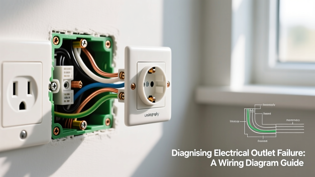
Installing a standard 15-amp duplex receptacle is often the first DIY electrical project homeowners attempt. However, treating an outlet electrical installation as a simple 'plug and play' task is a leading cause of residential arc faults and high-resistance heating. As of 2026, the National Electrical Code (NEC) has strictly enforced torque specifications and box-fill calculations that many older online tutorials completely ignore. This guide strips away the fluff and provides a professional-grade, beginner-friendly workflow for wiring a standard 120V outlet electrical box safely and to code.
Sourcing the Right Components (2026 Buyer's Matrix)
Do not buy the cheapest receptacle in the bulk bin. Budget-grade outlets feature thin brass contacts that loosen over time, leading to arcing. Below is the exact bill of materials for a reliable, code-compliant 15A circuit installation.
| Component | Recommended Model / Spec | 2026 Avg. Cost | Purpose & Expert Notes |
|---|---|---|---|
| Receptacle | Leviton T5320-W (15A Tamper-Resistant) | $1.75 | TR shutters prevent child shock hazards. Features deep back-wire clamps. |
| Electrical Box | Carlon B118W-UPC (18 cu. in. PVC) | $4.20 | 18 cubic inches prevents box-fill violations common with 14/2 pass-throughs. |
| Cable | Southwire 14/2 NM-B (Romex) | $0.65 / ft | 14 AWG copper for 15A circuits. Never use 14 AWG on a 20A breaker. |
| Wire Stripper | Klein Tools 11063W (Katapult) | $28.00 | Ensures exact 3/4-inch stripping without nicking the copper conductor. |
| Torque Tool | CDI 401SM Torque Screwdriver | $115.00 | Required by NEC 110.14(D) to achieve exact terminal tension. |
Understanding Outlet Electrical Box Fill Calculations
Before you mount the box, you must verify it is large enough for the wires entering it. NEC Article 314.16 dictates box fill based on cubic inches. A standard 14-cubic-inch box is often too small if you are passing power through to another downstream outlet.
The 18-Cubic-Inch Rule of Thumb
For 14 AWG wire, each conductor counts as 2.0 cubic inches. If your cable enters the box, and another cable leaves the box to feed the next room, you have:
- 4 Current-Carrying Conductors: (2 Hots, 2 Neutrals) = 8.0 cu. in.
- 1 Equipment Ground: (All grounds count as a single volume allowance) = 2.0 cu. in.
- Device Yoke: (The receptacle itself counts as 2 conductor volumes) = 4.0 cu. in.
- Total Required Volume: 14.0 cubic inches.
While a 14 cu. in. box is technically legal here, the physical bending radius of 14/2 NM-B cable makes stuffing it into a 14 cu. in. box a nightmare for beginners, often resulting in pinched wires. Always upgrade to an 18 cu. in. box (like the Carlon B118W-UPC) to give your hands and the wires adequate breathing room.
Step-by-Step Wiring Procedure
Ensure the breaker is OFF and verified with a non-contact voltage tester before touching any wires.
Step 1: Cable Entry and Jacket Stripping
Feed the 14/2 NM-B cable through the knockout. The outer PVC jacket must enter the box by at least 1/4 inch to 1/2 inch to protect the inner wires from the sharp plastic edges of the knockout. Strip exactly 8 inches of the outer jacket back from the entry point using a Romex rip tool.
Step 2: Precision Wire Stripping
Using the 14 AWG hole on your Klein wire strippers, strip exactly 3/4 inch of insulation from the black (hot) and white (neutral) wires. If you strip too little, the insulation will bind under the screw head. If you strip too much, you will expose bare copper outside the terminal, creating a severe shock and short-circuit hazard.
Step 3: Forming the J-Hook
Use the needle-nose pliers built into your wire stripper to bend a tight 'J-hook' at the end of the bare copper. The hook should be perfectly round and closed enough that it won't slip out from under the terminal screw when tightened.
Step 4: Terminal Connection (The Right Way)
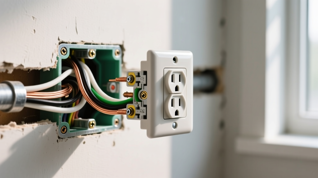
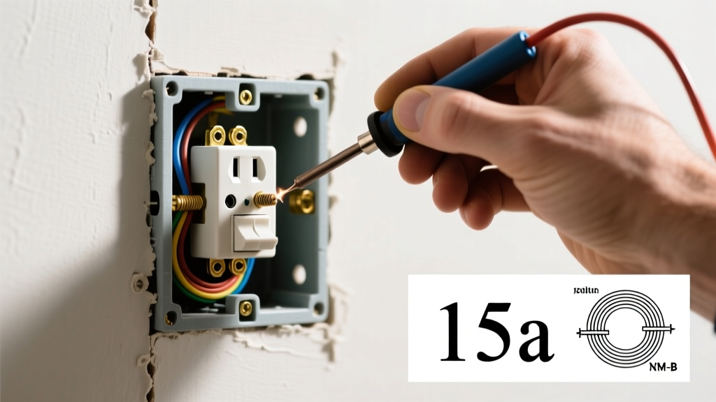
Loop the J-hook around the terminal screws in a clockwise direction. This ensures that as you tighten the screw (righty-tighty), the screw head pulls the wire hook tighter around the shaft rather than pushing it out. Connect the bare copper ground to the green grounding screw, the white wire to the silver terminal, and the black wire to the brass terminal.
The 2026 NEC Torque Requirement
CRITICAL CODE UPDATE: Under NEC 110.14(D), electrical equipment terminals must be tightened to the torque value specified by the manufacturer using a calibrated torque tool. Hand-tightening is no longer acceptable for new installations.
Most beginners simply crank the screwdriver until it feels tight. This causes two failure modes: under-torquing (leading to loose connections, arcing, and fires) and over-torquing (stripping the brass threads or snapping the screw head). The Leviton T5320-W receptacle requires exactly 14 inch-pounds of torque. Set your CDI torque screwdriver to 14 in-lbs, tighten the screw until the tool clicks, and stop immediately.
Common Beginner Failure Modes & Edge Cases
Even with the right tools, beginners frequently make structural errors that compromise the outlet electrical safety profile. Avoid these at all costs:
- The 'Backstab' Trap: Never use the push-in holes on the back of the receptacle (known as backstabbing). These rely on a tiny internal metal spring tab that loses tension over time due to thermal expansion and contraction. This creates high-resistance faults that melt the plastic housing. Always use the side-terminal screws or the screw-and-clamp back-wire plates.
- Reversed Polarity: Swapping the black and white wires. The hot wire (black) must always connect to the brass screw, which feeds the internal switch of any plugged-in appliance. Reversed polarity means an appliance is 'live' even when switched off.
- Pigtail Crowding: If you are connecting multiple neutral wires, use a yellow or red wire nut to join them with a 6-inch white pigtail that runs to the receptacle. Do not try to cram three 14 AWG wires under a single terminal screw.
- Missing TR Shutters: According to the Electrical Safety Foundation International (ESFI), Tamper-Resistant receptacles are required in all new residential builds to prevent children from inserting objects into the slots. Never bypass the TR mechanism or buy non-TR outlets for living spaces.
Testing and Verification
Once the receptacle is folded neatly into the box (push the wires straight back in a Z-fold, rather than cramming them in a ball) and the device is screwed to the yoke, restore power at the breaker.
Do not rely on a cheap $5 neon tester. Invest in a Klein Tools RT210 GFCI/Receptacle tester. Plug it into the newly installed outlet. You are looking for two solid yellow lights indicating 'Correct Wiring'. If you see a red light, you have an open ground or reversed polarity. Shut the breaker off immediately and re-verify your terminal connections and torque.
For comprehensive guidelines on residential electrical safety and arc-fault prevention, always refer to the latest NFPA 70 National Electrical Code and the Consumer Product Safety Commission's electrical safety resources. Proper planning and adherence to torque and box-fill specs will ensure your outlet electrical installation lasts for decades without thermal degradation.