
Understanding In Floor Electrical Outlet Architecture
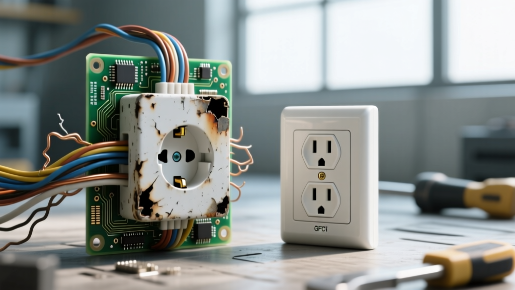
An in floor electrical outlet (commonly referred to as a floor box or floor receptacle) is a specialized wiring device designed to provide power, data, and AV connectivity in open-concept spaces where wall outlets are impractical. Unlike standard vertical wall receptacles, floor boxes are subjected to unique environmental and mechanical stressors, including foot traffic, rolling loads, aggressive floor cleaning chemicals, and moisture ingress from mopping or spills.
Whether installed in a commercial concrete slab or a residential wood-joist subfloor, these devices require rigorous inspection and testing protocols. A failing floor box doesn't just present a shock hazard; it creates a severe tripping hazard and can compromise the structural integrity of the surrounding flooring material. This comprehensive guide details the exact procedures for inspecting, testing, and troubleshooting in floor electrical outlets to ensure safety, functionality, and code compliance.
Essential Diagnostic Tools for Floor Receptacles
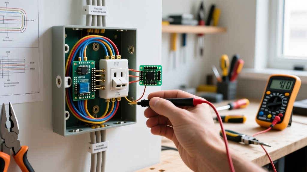
Before beginning any inspection, assemble the following professional-grade diagnostic tools. Relying on basic non-contact testers is insufficient for the complex grounding and polarity issues often found in shallow floor pans.
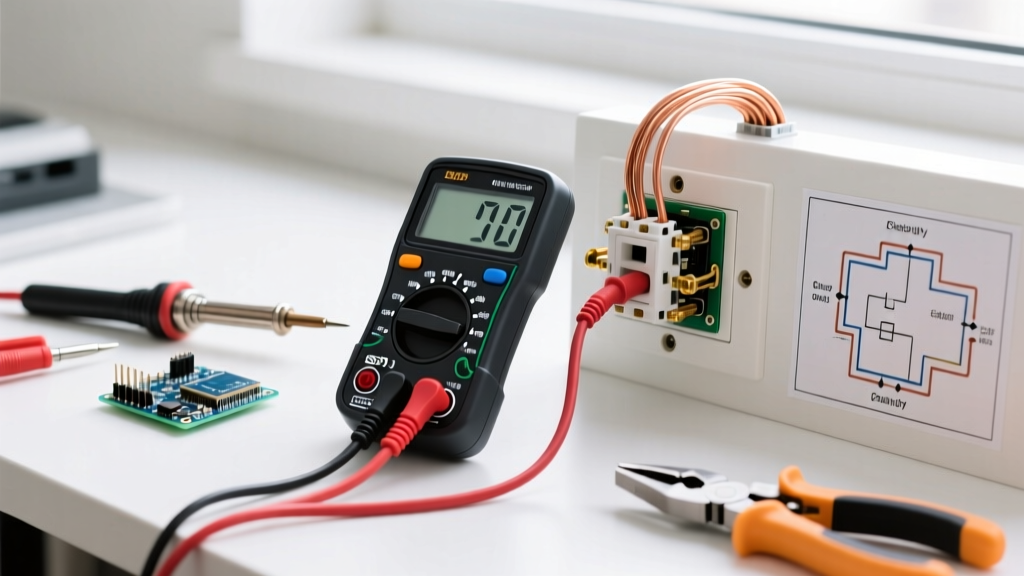
- Digital Multimeter (DMM): A True-RMS multimeter like the Fluke 117 (approx. $180-$220) is essential for accurate voltage readings, especially when dealing with potential induced voltages in long floor conduit runs.
- Receptacle Tester: The Klein Tools RT250 (approx. $35-$45) features a clear LCD screen that explicitly identifies wiring faults, including line/load reversal and ground continuity issues.
- Insulation Resistance Tester (Megger): For commercial installations, a Fluke 1587 FC insulation multimeter helps detect moisture-induced degradation in the wiring insulation inside concrete-encased floor boxes.
- Feeler Gauges and Depth Mics: To measure cover plate flushness and carpet flange clearances to prevent tripping hazards.
Phase 1: Physical and Environmental Inspection
The physical inspection of an in floor electrical outlet must address the mechanical interface between the electrical box and the finished floor. According to the Occupational Safety and Health Administration (OSHA), physical damage to electrical enclosures is a primary citation in commercial facility audits.
1. Cover Plate and Flush Mounting Verification
Floor boxes must sit perfectly flush with the finished floor. Use a straight edge and feeler gauge to check the gap between the cover plate and the floor surface.
- Hardwood/Tile Floors: The cover plate should not protrude more than 1/16 inch above the floor surface. Protrusion leads to plate warping when subjected to rolling office chairs or foot traffic.
- Carpeted Floors: Verify the carpet ring adjustment. Premium boxes like the Hubbell SystemOne feature a threaded carpet flange that adjusts from 1/4 inch to 3/8 inch to accommodate carpet and pad thickness. If the carpet is fraying around the edge, the flange is set too low and must be raised.
2. Gasket and Moisture Seal Integrity
Moisture is the number one enemy of floor receptacles. Inspect the neoprene or silicone gasket located between the cover plate and the floor box body. If the gasket shows signs of compression set (flattening beyond 20% of its original thickness), cracking, or chemical degradation from floor wax, it must be replaced immediately. In commercial settings, missing gaskets allow mop water to pool inside the shallow 3.5-inch or 4-inch deep pans, leading to catastrophic ground faults.
3. Concrete Encroachment and Box Deformation
For boxes poured into concrete slabs, inspect the interior walls of the box for concrete encroachment. If the pre-pour mud guard failed during the initial construction phase, concrete can compress the box walls, reducing the internal cubic inch capacity and crushing the internal wire insulation. Look for stress fractures in the PVC or galvanized steel walls of the box.
Phase 2: Electrical Testing and Verification
Once the physical integrity is confirmed, proceed to electrical testing. Always verify that the circuit is de-energized using a Category III or IV rated voltage tester before removing the cover plate to inspect the internal wiring terminations.
Step-by-Step Wiring Inspection
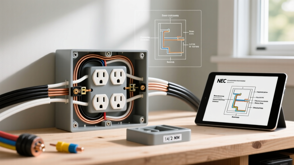
- Internal Volume Check: Floor boxes are notoriously shallow. Verify that the conductors are not tightly packed. According to NEC Article 314.16, the box must have adequate cubic inch capacity for the number and gauge of wires. Overstuffed floor boxes cause heat buildup and insulation puncture.
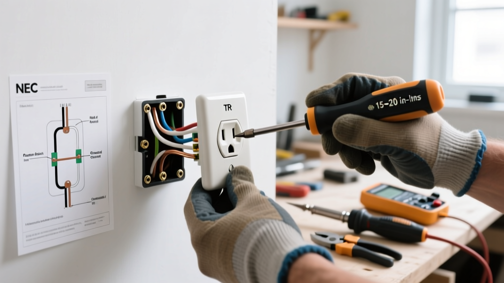
- Termination Torque: Inspect the brass and silver terminal screws on the receptacle. In floor boxes, vibrations from foot traffic can loosen standard terminations. Ensure wires are looped clockwise and tightly secured. Push-in (backstab) connections are strictly prohibited in floor boxes due to vibration-induced disconnects.
- Grounding Path Verification: The equipment grounding conductor (EGC) must be securely bonded to the metal floor box itself, not just the receptacle yoke. Use your multimeter in continuity mode to test the resistance between the receptacle ground pin and the metal floor box housing. It should read less than 1.0 ohm.
Live Circuit Testing
Restore power and use your True-RMS multimeter to verify voltage. You should read between 114V and 126V (Line-to-Neutral) and identical voltage (Line-to-Ground). A significant voltage drop between Neutral and Ground (greater than 2V) indicates a high-resistance neutral or an improperly bonded floor box conduit system.
Safety Warning: Never use a standard receptacle tester to trip a GFCI floor box if the circuit lacks a known good ground. The test button on most plug-in testers requires a functional equipment ground to divert current and trip the internal mechanism. If the ground is missing, the tester will falsely indicate the GFCI is functioning. Always use the built-in GFCI test button on the receptacle itself, as recommended by Fluke Corporation testing guidelines.
Common Floor Box Failure Modes and Diagnostics
The following matrix outlines specific failure modes unique to in floor electrical outlets, their root causes, and the required diagnostic fixes.
| Failure Mode | Primary Symptom | Root Cause | Diagnostic Fix & Action |
|---|---|---|---|
| Mop Water Intrusion | Intermittent GFCI tripping; corrosion on brass terminals. | Degraded cover gasket; missing threaded plug in unused duplex opening. | Replace neoprene gasket; install brass flush-mounted blanking plugs in all unused port openings. |
| Carpet Flange Misalignment | Frayed carpet edges; cover plate rocks when stepped on. | Flange set too low during installation; carpet pad compressed over time. | Rotate the threaded carpet ring counter-clockwise to raise the flange; trim excess carpet. |
| Line/Load Reversal | GFCI test button does not trip; downstream outlets are dead. | Wires stuffed blindly into shallow pan during rough-in. | Remove receptacle; verify LINE (source) and LOAD (downstream) markings; re-terminate correctly. |
| Concrete Encroachment | Receptacle sits proud of the cover; wires are pinched. | Pre-pour mud cover displaced during concrete screeding. | Chisel away intruding concrete; apply anti-oxidant paste to exposed wire insulation; verify cubic inch fill. |
NEC Code Compliance for Floor Boxes
As of the 2026 NEC adoption cycle, inspectors are heavily scrutinizing floor box installations under Article 314.27(B). The National Fire Protection Association (NFPA) explicitly mandates that floor boxes must be "listed for use in floors." You cannot legally install a standard metal or plastic wall box in a floor and cover it with a floor plate. The box must be specifically rated to withstand the crushing weight of foot traffic and environmental exposure.
Furthermore, in dwelling units, floor boxes are generally restricted from being installed in areas where they are subject to physical damage or where mop water is prevalent, unless they are specifically listed for such wet/damp locations. Commercial installations in open-plan offices must ensure that the floor box assembly maintains the fire rating of the floor/ceiling assembly if penetrating a fire-rated floor slab, often requiring specialized intumescent fire putty pads beneath the box.
Frequently Asked Questions (FAQ)
Can I install an in floor electrical outlet in an existing concrete slab?
Yes, but it requires core drilling and the use of a specific "core-drill" or "poke-through" floor box assembly (such as the Hubbell SystemOne core drill series). You must verify that you are not cutting through structural rebar or post-tension cables, which requires a ground-penetrating radar (GPR) scan before drilling. Expect to pay between $250 and $400 for the specialized box and concrete cutting labor, excluding the electrical wiring run.
Why does my floor outlet trip every time I plug in my vacuum?
Vacuums and floor buffers generate significant electromagnetic interference (EMI) and inrush current. If your floor outlet is GFCI protected, nuisance tripping is common. Ensure the GFCI receptacle is a modern, tamper-resistant, high-surge-immunity model (like the Pass & Seymour 2095TR), which is designed to filter out EMI noise from heavy motor loads without dropping the circuit.
Are data and AV ports in floor boxes tested the same way?
No. While power ports are tested for voltage and grounding, Cat6A or fiber optic data ports in floor boxes must be tested for insertion loss and crosstalk using a dedicated cable certifier (like the Fluke DSX CableAnalyzer). Floor boxes often feature tight 90-degree bend radii for data cables, which can easily exceed the minimum bend radius and cause packet loss if not properly dressed inside the shallow pan.