
The Hidden Danger of Daisy-Chained Workshop Receptacles
If you run a serious garage workshop, you already know the frustration of nuisance tripping. Table saws, welders, dust collectors, and air compressors draw massive startup surges that can easily overwhelm standard residential wiring. Most older homes and garages rely on 15-amp or 20-amp daisy-chained duplex receptacles. In this setup, power enters the first outlet, and a secondary set of wires 'pigtails' to the next outlet down the line.
This daisy-chain topology creates severe bottlenecks. The first receptacle in the chain carries the cumulative load of every tool plugged in downstream. Over time, the constant thermal cycling causes the wire insulation to become brittle, the backstab push-in connections to loosen, and the wire nuts to overheat. According to the Occupational Safety and Health Administration (OSHA), faulty wiring and overloaded circuits are leading causes of electrical fires in residential workshops. Upgrading to a centralized electrical outlet block—specifically a power distribution terminal block paired with heavy-duty receptacles—eliminates these failure points by utilizing a safer 'star' wiring topology.
What Exactly is an Electrical Outlet Block?
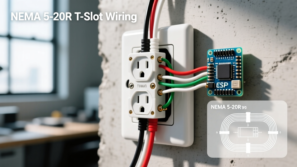
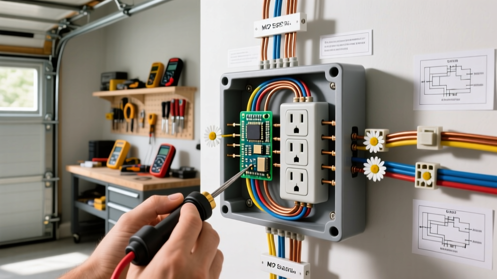
In the context of workshop and garage upgrades, an electrical outlet block refers to a heavy-duty power distribution terminal block housed within a secure enclosure. Instead of running a single 12 AWG wire from outlet to outlet, you run a large-gauge feeder wire (such as 6 AWG or 8 AWG) from your main panel directly into the electrical outlet block. The block then safely breaks down this high-amperage feed into multiple individual branch circuits, each protected by its own dedicated breaker or fused disconnect, feeding your heavy-duty receptacles independently.
This approach drastically reduces voltage drop, eliminates shared neutral overloading, and ensures that starting a 3-horsepower dust collector won't dim the lights or starve your table saw of voltage.
Terminal Power Blocks vs. Multi-Outlet Track Systems
When planning your upgrade, it is crucial to select the right type of block for your specific amperage requirements. Below is a comparison of the two primary upgrade paths.
| Feature | Terminal Distribution Block (Star Topology) | Surface Raceway Multi-Outlet Track |
|---|---|---|
| Best Application | High-draw stationary tools (Welders, CNC, Cabinet Saws) | Hand tools, battery chargers, workbench lighting |
| Max Amperacity | Up to 175A - 300A (Feeder dependent) | Typically limited to 20A per branch |
| Wiring Method | Individual home-runs to each receptacle | Continuous shared busbar or daisy-chain |
| Installation Complexity | High (Requires large enclosure, torque tools) | Low (Surface mount, plug-and-play) |
| Estimated Cost | $150 - $350 (Materials only) | $80 - $150 |
Step-by-Step Upgrade: Installing a Power Distribution Block
Upgrading your garage wiring is not a beginner DIY project; it requires a solid understanding of the National Electrical Code (NEC) and strict adherence to safety protocols. If you are not comfortable working inside a live electrical panel, hire a licensed electrician to run the main feeder while you handle the block termination and receptacle mounting.
Step 1: Isolate and Verify the Circuit
Shut off the main breaker supplying the garage subpanel. Use a non-contact voltage tester, followed by a digital multimeter like the Fluke T6-1000, to verify zero voltage across all hot, neutral, and ground busbars. Lockout/tagout (LOTO) the panel to prevent accidental re-energizing.
Step 2: Mount the Block Enclosure
For a robust setup, mount a NEMA 4X fiberglass or heavy-gauge steel enclosure centrally in your workshop. A popular, highly reliable choice is the Mersen MPDB63033 Power Distribution Block (rated for 175 amps). This block features a clear polycarbonate cover, allowing for easy visual inspection of the terminations without exposing live parts.
Step 3: Terminate the Feeder and Branch Wires
Strip your main feeder wire using a heavy-duty wire stripper. For a 60-amp subpanel feed using 6 AWG THHN copper, strip exactly 5/8-inch of insulation. Insert the wire into the primary line lug of the electrical outlet block. For the branch circuits feeding your individual 20-amp receptacles, use 12 AWG THHN wire and terminate them into the load-side lugs.
Expert Warning: Never use standard needle-nose pliers to tighten terminal block set screws. Improper torque is the number one cause of terminal arcing and subsequent fires. Always use a calibrated torque screwdriver.
Step 4: Torque to Manufacturer Specifications
NEC 110.14(D) strictly mandates that all electrical connections must be torqued to the manufacturer's specified values. For the Mersen MPDB series, the set screws typically require 45 in-lbs of torque for larger gauge wires, and 20 in-lbs for 12 AWG branch wires. Use a calibrated torque screwdriver (such as the Klein Tools 70907) to ensure exact compliance.
Step 5: Wire the Heavy-Duty Receptacles
Run your individual branch circuits from the outlet block to your workstations. Terminate them into industrial-grade receptacles like the Leviton 5366. Avoid 'backstabbing' the wires; always use the side-binding screw terminals and loop the wire clockwise around the screw to ensure the tightening action pulls the loop closed.
NEC 2026 Compliance & Sizing Your Block
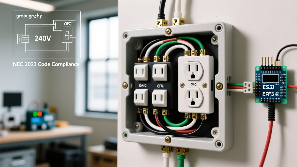
When upgrading to an electrical outlet block, you must adhere to the latest National Electrical Code standards. The National Fire Protection Association (NFPA 70) outlines strict rules for box fill, wire bending radius, and overcurrent protection.
- Box Fill Calculations (NEC Article 314): The enclosure housing your electrical outlet block must be large enough to dissipate heat and allow for proper wire bending. If you are using a 6 AWG feeder, NEC Table 312.6(A) requires a minimum wire bending space of 2.5 inches from the lug to the enclosure wall.
- Overcurrent Protection: The feeder breaker in your main panel must be sized to protect the weakest link in your system. If your electrical outlet block is rated for 175A, but your feeder wire is 6 AWG copper (rated for 65A at 75°C), your main breaker cannot exceed 60 amps.
- Grounding and Bonding: The metal enclosure of the outlet block must be bonded to the equipment grounding conductor. Use a green grounding screw or a listed grounding lug to bond the enclosure to the ground busbar.
Cost Breakdown & Recommended 2026 Models
Investing in a proper electrical outlet block setup costs more upfront than standard daisy-chained outlets, but the return on investment in safety, tool longevity, and reduced downtime is substantial. Below is a realistic material cost breakdown for a 4-circuit workshop upgrade.
| Component | Recommended Model | Estimated Price |
|---|---|---|
| Power Distribution Block | Mersen MPDB63033 (175A) | $65.00 |
| NEMA 4X Enclosure | Bud Industries NBF-32044 | $42.00 |
| Industrial Receptacles (x4) | Leviton 5366 (20A, 125V) | $72.00 ($18 ea) |
| Torque Screwdriver | Klein Tools 70907 | $115.00 |
| Wire (12 AWG THHN) | Southwire (500 ft spool) | $95.00 |
| Total Estimated Material Cost | $389.00 |
Frequently Asked Questions
Can I use a standard plastic junction box for my electrical outlet block?
No. Standard PVC junction boxes are not rated to handle the physical stress, heat dissipation, or mounting requirements of heavy-duty terminal distribution blocks. You must use a listed, adequately sized metal or fiberglass industrial enclosure that provides proper wire bending radii as dictated by NEC Article 314.
Do I need to use anti-oxidant paste on the terminal lugs?
If you are terminating aluminum wire into the electrical outlet block, applying a UL-listed anti-oxidant compound (such as Noalox) is mandatory to prevent galvanic corrosion and high-resistance connections. If you are using copper wire, it is generally not required, though some manufacturers still recommend it for outdoor or high-humidity garage environments. Always consult the UL Electrical Safety Guidelines and the specific block manufacturer's instructions.
How do I balance the load across the block?
If your electrical outlet block is fed by a 240V split-phase feeder, you must balance your 120V branch circuits evenly across the two hot legs (L1 and L2). Use a clamp meter to measure the current draw on both legs while your primary tools are running. An imbalanced load will cause excessive current on the shared neutral wire, leading to overheating and potential failure.