
Decoding the Blueprint: Your First Step to a Safe Installation
Staring at a set of architectural blueprints for the first time can feel like trying to read an ancient dialect. For a beginner electrician or an ambitious DIYer, the electrical outlet symbol on a floor plan is the critical bridge between a theoretical design and a safe, code-compliant physical installation. Misinterpreting these symbols doesn't just lead to aesthetic issues; it results in failed inspections, torn-out drywall, and potential fire hazards.
Before you pick up a reciprocating saw to cut into a stud or pull a single foot of Romex, you must understand exactly what the architect and electrical engineer intended. This guide will break down standard blueprint symbology, translate those symbols into National Electrical Code (NEC) requirements, and walk you through the physical rough-in and wiring process using 2026 industry standards.
The Anatomy of Electrical Outlet Symbols
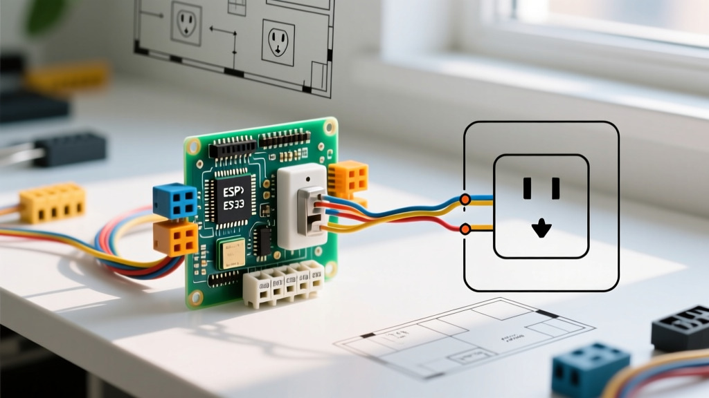
Architectural and electrical drawings rely on standardized symbols, largely governed by ANSI/IEEE 315 and industry conventions. While minor variations exist between firms, the core symbols remain consistent. Below is a master translation chart for the most common receptacle symbols you will encounter on a residential or light-commercial floor plan.
| Symbol Description | Meaning & Application | NEC / Code Consideration |
|---|---|---|
| Circle with two parallel vertical lines | Standard Duplex Receptacle: The baseline 15A or 20A outlet. | Must be on a general lighting branch circuit (NEC 210.52). |
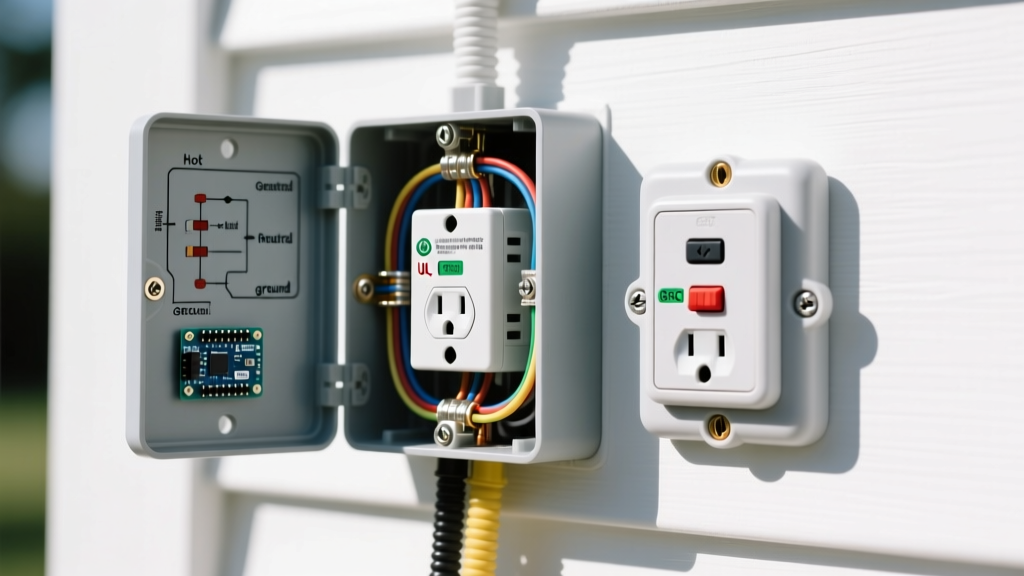
| Circle with parallel lines + 'GFCI' | Ground Fault Circuit Interrupter: Required in wet/damp locations. | Mandatory within 6 feet of sinks, in garages, and outdoors (NEC 210.8). |
| Circle with parallel lines + 'AFCI' | Arc Fault Circuit Interrupter: Protects against parallel arcing. | Required in bedrooms, living rooms, and kitchens (NEC 210.12). |
| Circle with a diagonal shaded half | Split-Wired (Half-Hot): One half switched, one half always hot. | Requires a 3-wire (12/3 or 14/3) cable and breaking the brass fin. |
| Circle with 'WP' or an inverted triangle | Weatherproof / Exterior: Must use an in-use bubble cover. | Requires weather-resistant (WR) rated receptacles and covers. |
| Circle with a cross or 'FL' | Floor Receptacle: Installed in a floor box assembly. | Only counts as a required wall outlet if within 18 inches of the wall. |
Translating Symbols to NEC Spacing Rules
Finding the electrical outlet symbol on a floor plan is only half the battle; you must also understand the invisible spacing rules that dictate where those symbols are allowed to be placed. The National Fire Protection Association (NFPA 70) outlines strict spacing requirements in Article 210.52 to prevent homeowners from using dangerous extension cords.
The 6-Foot / 12-Foot Rule (Living Areas)
In living rooms, bedrooms, and hallways, no point along the floor line of any wall can be more than 6 feet from a receptacle. This effectively means outlets must be spaced no more than 12 feet apart. Furthermore, any isolated wall space that is 2 feet or wider (including space measured around corners) requires its own dedicated outlet symbol on the plan.
Kitchen Countertop Rules
Kitchen islands and peninsulas have their own rigorous demands. Countertop receptacles must be installed so that no point along the wall line is more than 24 inches from an outlet. As of the latest NEC updates, islands require at least one receptacle if the island is 24 inches or more in length, and they must be fed by a dedicated 20A small-appliance branch circuit.
From Blueprint to Reality: Rough-In Preparation
Once you have verified the floor plan symbols against NEC spacing, it is time to transfer those marks to the physical studs. This phase requires precision. A crooked box or an incorrectly placed stud bay will haunt you during the drywall and trim phases.
- Establish Finished Floor Level (FFL): Never measure from the subfloor. Use a Bosch GLL 55 laser level to shoot a benchmark line around the room. Standard outlet height is 12 inches Above Finished Floor (AFF). If the project requires ADA compliance, the ADA Design Standards mandate receptacles be placed between 15 and 48 inches AFF.
- Mark the Stud Bays: Hold your electrical box against the stud and mark the cut lines. Always mount boxes on the side of the stud that faces the center of the room to avoid nail-plate conflicts with drywall screws.
- Select the Correct Box Volume: This is where beginners fail. A standard 1-gang box (like the Carlon B618R-UPC) offers 18 cubic inches of space. According to NEC Article 314.16, every 12 AWG wire counts as 2.25 cubic inches. If you are pushing four 12/2 cables into a single box to daisy-chain outlets, you will exceed the 18 cubic inch limit and fail inspection. Upgrade to a 22.5 or 25 cubic inch deep box (approx. $2.50 to $4.00 each) for high-volume junctions.
Wiring Execution: Torque and Terminations
With the boxes secured and the drywall hung, you move to the final wiring phase. The physical installation of the receptacle requires adherence to modern torque specifications. Gone are the days of simply tightening the screw until it 'feels tight'.
The Torque Screwdriver Mandate
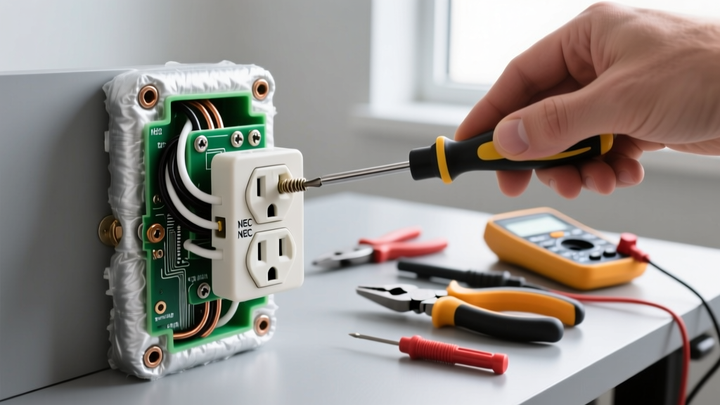
Under NEC 110.14(D), any electrical equipment with terminals rated 100 amps or less must be tightened using a calibrated torque tool. For a standard Leviton 5262 15A duplex receptacle, the manufacturer specifies a torque of 14 in-lbs. Using a tool like the Milwaukee 48-22-5101 torque screwdriver ensures you do not under-torque (leading to arcing and fires) or over-torque (stripping the brass terminal threads).
Stripping and Looping
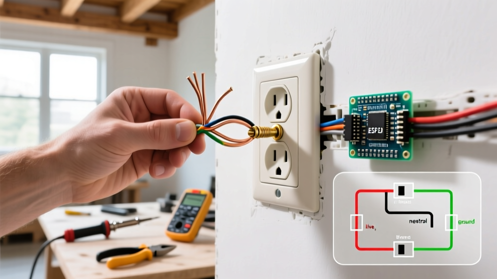
Use dedicated wire strippers (e.g., Klein Tools 11055) to remove exactly 3/4 inch of insulation from the 12 AWG THHN or NM-B conductors. When wrapping the wire around the terminal screw, always loop it clockwise. This ensures that as the screw tightens, the loop pulls tighter around the shaft rather than splaying outward.
Expert Warning: The Break-Off Fin Trap
Look closely at the brass (hot) side of your duplex receptacle. There is a small metal connecting fin between the top and bottom terminal screws. Do not break this fin unless the floor plan specifically calls for a split-wired (half-hot) receptacle controlled by a wall switch. Breaking this fin on a standard daisy-chained outlet will result in the bottom half of the outlet being completely dead, a classic beginner mistake that requires pulling the device back out to install a pigtail jumper.
Final Inspection and Testing
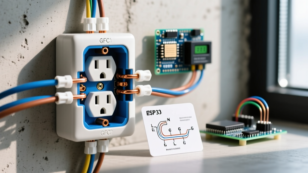
Before energizing the panel, perform a visual audit. Ensure all ground wires are pigtailed together with a green wire nut and attached to the green grounding screw. Verify that no bare copper ground wire is touching the brass hot terminal. Once the breaker is flipped, use a receptacle analyzer (like the Klein Tools RT210, approx. $16) to verify correct wiring, open grounds, or reversed polarity.
Mastering the electrical outlet symbol on a floor plan is about more than just recognizing shapes; it is about understanding the lifecycle of the circuit from the architect's pen to the final OSHA and local AHJ safety inspections. By combining blueprint literacy with strict adherence to box-fill calculations and torque specifications, you guarantee a safe, professional-grade installation every time.