
The Evolution of Mobile Power: Diagnosing the F-150 Pro System
The integration of high-capacity inverters into modern trucks has fundamentally changed how contractors and outdoor enthusiasts use their vehicles. However, when a Ford F-150 electric outlet stops delivering power, the diagnosis is rarely as simple as checking a standard residential breaker. Whether you are operating a 2024-2026 F-150 PowerBoost Hybrid with the 7.2kW Pro Power Onboard system, or an F-150 Lightning with the 9.6kW extended-range inverter, the electrical architecture relies on a complex network of high-current contactors, pure sine wave inverters, and software-driven ground fault protections.
Unlike a static home panel, the truck's power system is subject to vibration, thermal cycling, and strict automotive safety protocols. According to Ford's official F-150 specifications, the Pro Power system is designed to mimic a residential grid, but it includes aggressive automated shutoffs to protect the vehicle's high-voltage traction battery. This guide provides a deep-dive, technician-level diagnostic framework for isolating and resolving outlet failures in both the cabin and the truck bed.
System Architecture: Know Your Inverter Tier
Before pulling fuses, you must identify which inverter topology your truck utilizes. The diagnostic path for a dead 120V cabin outlet differs vastly between the 2.0kW and 7.2kW systems.
| Inverter Tier | Common Models (2021-2026) | Bed Outlet Configuration | Cabin Outlet Limit | Main BJB Fuse Rating |
|---|---|---|---|---|
| 2.0 kW | PowerBoost Hybrid (Base) | Two 120V 20A (NEMA 5-20) | 150W (via DC-AC inverter) | 15A / 20A Mini Fuses |
| 2.4 kW | F-150 Lightning (Standard) | Four 120V 20A (NEMA 5-20) | 120V 20A (NEMA 5-20) | 30A Mega Fuse |
| 7.2 kW | PowerBoost Hybrid (Max) | Four 120V + One 240V 30A (NEMA L14-30) | 120V 20A (NEMA 5-20) | 60A / 80A Mega Fuse |
| 9.6 kW | F-150 Lightning (Extended) | Four 120V + One 240V 30A (NEMA L14-30) | 120V 20A (NEMA 5-20) | 100A Mega Fuse |
Phase 1: The GFCI Cascade and Software Lockouts
The most common reason for a completely dead Ford F-150 electric outlet bed panel is not a blown fuse, but a software-induced lockout triggered by a Ground Fault Circuit Interrupter (GFCI) event. The National Electrical Code (NEC), as outlined by the NFPA 70 standards, mandates strict ground-fault protection for outdoor and damp-location receptacles. Ford implements this via a master GFCI module located behind the bed outlet faceplate.
The 30-Second Capacitor Drain Reset
If you plug in a faulty compressor or a tool with a degraded ground wire, the bed GFCI will trip. On the 7.2kW and 9.6kW systems, this doesn't just cut power to the bed; it signals the Body Control Module (BCM) to open the high-voltage contactors, disabling the entire Pro Power system to prevent backfeed or electrocution hazards.
- Disconnect all loads: Unplug every device from both the bed and cabin outlets.
- Power down the inverter: Use the center touchscreen to toggle Pro Power OFF, or turn the truck completely off and exit the vehicle with the key fob at least 10 feet away.
- Wait 30 seconds: This allows the inverter's internal DC-link capacitors to discharge and the main contactors to physically open.
- Locate the physical reset: On the bed outlet panel, locate the small, illuminated GFCI reset button between the 120V duplex receptacles. Press it firmly until it clicks.
- Re-engage the system: Turn the truck on, navigate to the Pro Power menu, and toggle the system ON. Check the dashboard for a 'System Ready' message.
Phase 2: Diagnosing the Neutral-Ground Bond Edge Case
A highly specific, yet frequently encountered, failure mode occurs when users attempt to connect their F-150's 240V NEMA L14-30 twist-lock outlet to a residential manual transfer switch for home backup power. If the Ford F-150 electric outlet immediately trips the moment the transfer switch is engaged, you are experiencing a Neutral-Ground Bond Fault.
Expert Insight: Residential main panels have a physical bonding screw that ties the neutral bus bar to the ground bus bar. The Pro Power Onboard inverter creates its own floating neutral. If you plug the truck into a panel that already has a neutral-ground bond, the inverter's internal sensors will detect a parallel neutral path, interpret it as a massive ground fault, and instantly shut down the 240V output to prevent circulating currents.
The Fix: You must install a transfer switch that explicitly features a 'Switched Neutral' (or isolated neutral) configuration. This ensures the neutral-ground bond is only made at the truck's inverter when running on Pro Power, and switches back to the utility's bond when grid power is restored. Refer to SAE International guidelines on mobile power interconnections for safe transfer switch topologies.
Phase 3: High-Current Fuse and Contactor Verification
If the GFCI is reset, the touchscreen shows 'Pro Power On', but the outlets remain dead, the fault likely lies upstream in the Battery Junction Box (BJB) or the Passenger Distribution Box (PDB).
Locating the Pro Power Mega Fuses
For the 2.4kW, 7.2kW, and 9.6kW systems, the high-voltage DC feed from the traction battery to the inverter is protected by large bolt-down Mega Fuses located in the under-hood BJB.
- Visual Inspection is Insufficient: A blown 60A or 100A Mega fuse will not always show a visibly broken element through the plastic window due to the arc-quenching sand inside.
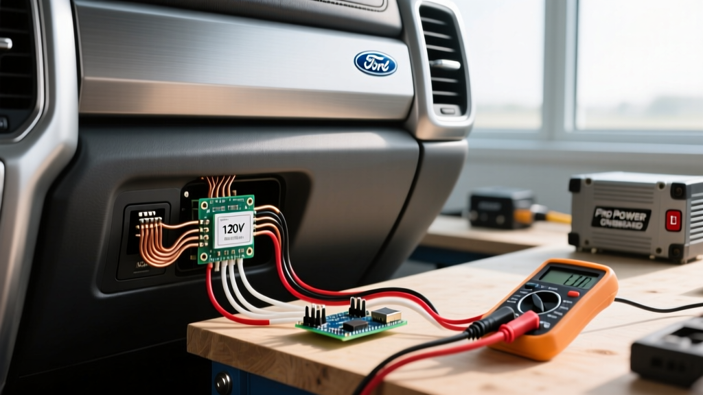
- Multimeter Testing: Set your digital multimeter to continuity or resistance. Remove the BJB cover, unbolt the suspect Mega fuse, and probe the terminals. A reading of 'OL' (Open Loop) confirms a blown fuse.
- Root Cause Warning: Mega fuses in the Pro Power system do not blow from standard overloads; the software will throttle or shut down the inverter before the fuse melts. If a BJB Mega fuse is blown, it indicates a catastrophic short circuit, often caused by water intrusion into the bed outlet harness, rodent damage to the inverter DC cables, or a failed internal IGBT (Insulated-Gate Bipolar Transistor) bridge inside the inverter itself.
Phase 4: Thermal Derating and Environmental Shutoffs
The F-150's inverter is liquid-cooled, sharing a cooling loop with the vehicle's power electronics. However, the bed outlets are exposed to ambient conditions. If you are running a continuous 15A load (like a space heater or a large air compressor) in the bed during peak summer temperatures, the system may initiate a thermal derating protocol.
Symptoms of Thermal Overload
Unlike a hard fault that throws a dashboard warning code, thermal derating often manifests as intermittent power loss. The outlet will work for 10 minutes, shut off for 5 minutes, and then reactivate. This is governed by the inverter's internal thermistors. If the internal heat sink exceeds 113°F (45°C) above ambient baseline, the software will pulse-width modulate the contactors to drop the voltage, effectively starving the load to force a cooldown. If you experience this, reduce the continuous draw to under 12A (approx. 1400W) per 120V circuit, or move the load to the climate-controlled cabin outlet if your tier supports it.
Quick Diagnostic Matrix: Symptom to Solution
| Symptom | Probable Failure Point | Diagnostic Action |
|---|---|---|
| All bed and cabin outlets dead; Pro Power toggles OFF automatically. | Master GFCI Trip or Ground Fault. | Perform 30-second capacitor drain and press physical bed GFCI reset. |
| Bed outlets work, but cabin 120V outlet is dead. | Cabin-specific PDB fuse or localized wiring fault. | Check Passenger Distribution Box for the 20A mini-fuse labeled 'IP/Pwr Point'. |
| 240V L14-30 outlet trips immediately upon plugging into house. | Neutral-Ground Bond conflict. | Verify transfer switch has a switched/isolated neutral configuration. |
| Touchscreen shows 'Pro Power Fault - Service Required' (U3000 codes). | Inverter internal fault or BJB Mega Fuse blown. | Test BJB Mega fuses for continuity; inspect bed harness for chafing/water. |
| Outlets work intermittently under heavy load in hot weather. | Thermal Derating Protocol. | Reduce continuous load to <1400W per circuit; ensure bed airflow is unobstructed. |
When to Seek Dealer-Level Diagnostics
If you have verified the GFCI reset, confirmed the Mega fuses have continuity, and ensured no neutral-ground bond conflicts exist, the issue may reside within the High-Voltage Inverter Module (HVIM) itself. The 2024-2026 F-150 models utilize advanced Over-The-Air (OTA) software updates that occasionally require a module reflash if the BCM and HVIM lose communication synchronization. Furthermore, opening the sealed HVIM casing voids the high-voltage warranty and poses a severe arc-flash and electrocution risk due to the 400V+ DC architecture. If the diagnostic matrix above does not resolve the dead Ford F-150 electric outlet, it is time to connect the vehicle to Ford's FDRS (Ford Diagnostic and Repair System) at a certified EV/Hybrid dealership to pull the proprietary HVIM PID data.